Toyota 4Runner: On-vehicle Inspection
ON-VEHICLE INSPECTION
PROCEDURE
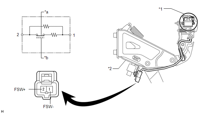
1. INSPECT BRAKE PEDAL LOAD SENSING SWITCH
HINT:
- Do not remove the brake pedal load sensing switch from the brake pedal lever sub-assembly.
- When there is a malfunction in the brake pedal load sensing switch, replace the brake pedal lever sub-assembly.
- The illustration below is for LHD vehicles. Check the brake pedal load sensing switch for RHD vehicles using the same procedure as for LHD vehicles.
(a) Disconnect the brake pedal load sensing switch connector.
 Text in Illustration
|
*1 |
Brake Pedal Load Sensing Switch |
*2 |
Brake Pedal Support Assembly |
|
*a |
Brake Pedal Released (ON) |
*b |
Brake Pedal Depressed (OFF) |
(b) Measure the resistance according to the value(s) in the table below.
Standard Resistance:
|
Tester Connection |
Condition |
Specified Condition |
|---|---|---|
|
2 (FSW+) - 1(FSW-) |
Brake pedal depressed |
0.9 to 1.1 kΩ |
|
Brake pedal released |
192 to 234 Ω |
If the result is not as specified, replace the brake pedal support assembly (See
page .gif) ).
).
 Components
COMPONENTS
ILLUSTRATION
...
 Removal
REMOVAL
CAUTION / NOTICE / HINT
PROCEDURE
1. DISCONNECT CABLE FROM NEGATIVE BATTERY TERMINAL
CAUTION:
Wait at least 90 seconds after disconnecting the cable from the negative (-)
battery termin ...
Other materials about Toyota 4Runner:
Clearance Warning Ecu
Components
COMPONENTS
ILLUSTRATION
Removal
REMOVAL
PROCEDURE
1. DISCONNECT CABLE FROM NEGATIVE BATTERY TERMINAL
CAUTION:
Wait at least 90 seconds after disconnecting the cable from the negative (-)
battery terminal to disable the SRS system.
N ...
Removal
REMOVAL
CAUTION / NOTICE / HINT
HINT:
Use the same procedure for the RH and LH sides.
The procedure listed below is for the LH side.
PROCEDURE
1. REMOVE ROOF HEADLINING ASSEMBLY
(a) Remove the roof headlining assembly (See page
).
2. ...

0.0158