
Toyota 4Runner: Removal
REMOVAL
CAUTION / NOTICE / HINT
PROCEDURE
1. DISCONNECT CABLE FROM NEGATIVE BATTERY TERMINAL
CAUTION:
Wait at least 90 seconds after disconnecting the cable from the negative (-) battery terminal to disable the SRS system.
NOTICE:
When disconnecting the cable, some systems need to be initialized after the cable
is reconnected (See page .gif) ).
).
2. REMOVE LOWER NO. 1 INSTRUMENT PANEL AIRBAG ASSEMBLY
(a) Remove the lower No. 1 instrument panel airbag assembly (See page
).
3. REMOVE BRAKE PEDAL RETURN SPRING
4. REMOVE PUSH ROD PIN
(a) Remove the clip and push rod pin from the brake pedal.
5. REMOVE STOP LIGHT SWITCH ASSEMBLY
(a) Disconnect the stop light switch connector.
(b) Remove the stop light switch assembly (See page
).
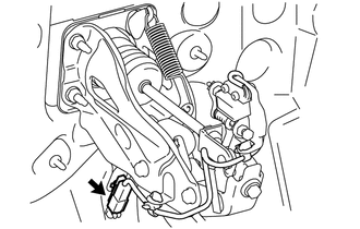
6. DISCONNECT BRAKE PEDAL LOAD SENSING SWITCH
|
(a) Disconnect the brake pedal load sensing switch connector. |
|
7. REMOVE BRAKE PEDAL SUPPORT ASSEMBLY
|
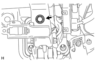
(a) Remove the brake pedal support reinforcement set bolt. |
|
(b) Remove the brake master cylinder sub-assembly (See page
).
(c) Remove the brake booster assembly (See page
).
|
(d) Remove the 4 nuts and brake pedal support assembly. |
|
.png)
 On-vehicle Inspection
ON-VEHICLE INSPECTION
PROCEDURE
1. INSPECT BRAKE PEDAL LOAD SENSING SWITCH
HINT:
Do not remove the brake pedal load sensing switch from the brake pedal
lever sub-assembly.
When the ...
 Disassembly
DISASSEMBLY
PROCEDURE
1. REMOVE BRAKE PEDAL PAD
(a) Remove the brake pedal pad from the brake pedal sub-assembly.
2. REMOVE STOP LIGHT SWITCH MOUNTING ADJUSTER
(a) Remove the stop light switch mo ...
Other materials about Toyota 4Runner:
Operation Check
OPERATION CHECK
1. AUTOMATIC LIGHT CONTROL SYSTEM OPERATION CHECK
(a) Turn the ignition switch to ON.
(b) Turn the headlight dimmer switch to the AUTO position.
(c) Cover the automatic light control sensor.
(d) Check that the taillights and low beam headl ...
Open in Motor LH Circuit (22,24)
DESCRIPTION
When there is an open in the side auto step motor circuit, the side auto step
controller ECU assembly does not operate the automatic running board.
DTC No.
Detection Condition
Trouble Area
22
...

0.0305