Toyota 4Runner: Only Wireless Control Function is Inoperative
DESCRIPTION
The door control receiver receives signals from the transmitter and sends these signals to the main body ECU. The main body ECU then controls all the doors by sending lock/unlock signals to each door.
WIRING DIAGRAM
.png)
CAUTION / NOTICE / HINT
NOTICE:
- Inspect the fuses for circuits related to this system before performing the following inspection procedure.
- When replacing the door control receiver, refer to the registration
procedures (See page
.gif) ).
).
PROCEDURE
|
1. |
CHECK POWER DOOR LOCK OPERATION |
(a) Check the power door lock operation (See page
).
OK:
Each door locks and unlocks normally.
| NG | .gif) |
Go to POWER DOOR LOCK CONTROL SYSTEM |
|
.gif)
|
2. |
CHECK KEY REMINDER WARNING OPERATION |
(a) Check the key reminder buzzer operation (See page
).
HINT:
If the key reminder buzzer is functioning normally, it can be assumed that the unlock warning switch is also functioning normally.
OK:
Key reminder buzzer operates normally.
| NG | |
Go to KEY REMINDER WARNING SYSTEM |
|
|
3. |
CHECK WIRELESS DOOR CONTROL TRANSMITTER |
(a) Check whether the wireless door lock control functions operate normally with another registered transmitter.
OK:
Wireless door lock control functions operate normally.
| NG | |
GO TO STEP 5 |
|
|
4. |
CHECK TRANSMITTER BATTERY |
(a) Remove the battery from the inoperative wireless door control transmitter
(See page ).
(b) Measure the voltage according to the value(s) in the table below.
Standard Voltage:
|
Tester Connection |
Condition |
Specified Condition |
|---|---|---|
|
Battery positive (+) - Battery negative (-) |
Always |
2.5 to 3.2 V |
| OK | |
REPLACE DOOR CONTROL TRANSMITTER |
| NG | |
REPLACE TRANSMITTER BATTERY |
|
5. |
CHECK FOR ELECTRICAL NOISE |
(a) Move the transmitter in the vicinity of the door control receiver.
HINT:
Refer to Parts Location for the location of the door control receiver (See page
).
(b) Press and hold either the lock or unlock transmitter switch for 1 second, and check that the doors are locked or unlocked accordingly.
OK:
Wireless door lock control functions operate normally.
HINT:
- Check if electrical noise is the cause by moving the door control transmitter closer to the door control receiver. Moving closer will decrease the effects of electrical noise.
- If the operation check can be performed normally, there is a high probability that electrical noise or a decrease in output from the door control transmitter is the cause of the malfunction. There is a high probability that electrical noise is the cause if the problem occurs only in a certain location or only during a certain time of day. Also, custom components may be causing electrical noise. If custom components are installed in the vehicle, remove them and perform the operation check again.
| OK | |
FIND CAUSE OF ELECTRICAL NOISE AND REMOVE IT |
|
|
6. |
CHECK HARNESS AND CONNECTOR (DOOR CONTROL RECEIVER - MAIN BODY ECU) |
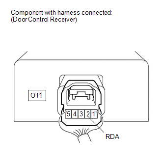
(a) Disconnect the O11 receiver connector.
(b) Disconnect the F9 ECU connector.
(c) Measure the resistance according to the value(s) in the table below.
Standard Resistance:
|
Tester Connection |
Condition |
Specified Condition |
|---|---|---|
|
O11-2 (RDA) - F9-26 (RDA) |
Always |
Below 1 Ω |
|
O11-3 (PRG) - F9-25 (PRG) |
||
|
O11-2 (RDA) or F9-26 (RDA) - Body ground |
Always |
10 kΩ or higher |
|
O11-3 (PRG) or F9-25 (PRG) - Body ground |
| NG | |
REPAIR OR REPLACE HARNESS OR CONNECTOR |
|
|
7. |
CHECK HARNESS AND CONNECTOR (DOOR CONTROL RECEIVER - BATTERY AND BODY GROUND) |
|
(a) Disconnect the O11 receiver connector. |
|
.png)
(b) Measure the resistance and voltage according to the value(s) in the table below.
Standard Resistance:
|
Tester Connection |
Condition |
Specified Condition |
|---|---|---|
|
O11-1 (GND) - Body ground |
Always |
Below 1 Ω |
Standard Voltage:
|
Tester Connection |
Condition |
Specified Condition |
|---|---|---|
|
O11-5 (+B) - Body ground |
Always |
11 to 14 V |
|
*a |
Front view of wire harness connector (to Door Control Receiver) |
| NG | |
REPAIR OR REPLACE HARNESS OR CONNECTOR |
|
|
8. |
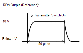
CHECK DOOR CONTROL RECEIVER (OUTPUT) |
(a) Using an oscilloscope, check the waveform.
 Measurement Condition
|
Item |
Content |
|---|---|
|
Tester Connection |
O11-2 (RDA) - Body ground |
|
Tool Setting |
10 V/DIV., 50 μsec./DIV. |
|
Condition |
No key in ignition key cylinder, all doors closed and transmitter switch off → on |
OK:
Waveform is output normally (refer to illustration).
| OK | |
REPLACE MAIN BODY ECU (MULTIPLEX NETWORK BODY ECU) |
| NG | |
REPLACE DOOR CONTROL RECEIVER |
 Wireless Door Lock Tuner Circuit Malfunction (B1242)
DESCRIPTION
The door control receiver receives signals from the transmitter and sends these
signals to the main body ECU. This DTC is stored when the applicable RDA signal
cannot be received with ...
 No Answer-Back
DESCRIPTION
In some cases, the wireless door lock control functions are normal but the hazard
warning light and/or wireless door lock buzzer answer-back function(s) does not
operate. In such case ...
Other materials about Toyota 4Runner:
Four-wheel drive system (part-time 4WD models)
Use the front-wheel drive control lever or switch to select the following
transfer modes:
Type A
The four-wheel drive indicator comes on when H4, N or L4 mode is selected.
1. H2 (high speed position, two-wheel drive)
Use this for normal driving on dry ...
Removal
REMOVAL
PROCEDURE
1. DISCONNECT CABLE FROM NEGATIVE BATTERY TERMINAL
NOTICE:
When disconnecting the cable, some systems need to be initialized after the cable
is reconnected (See page ).
2. REMOVE UPPER RADIATOR SUPPORT SEAL
3. REMOVE FRONT FENDER MAI ...

0.0093