Toyota 4Runner: Wireless Door Lock Tuner Circuit Malfunction (B1242)
DESCRIPTION
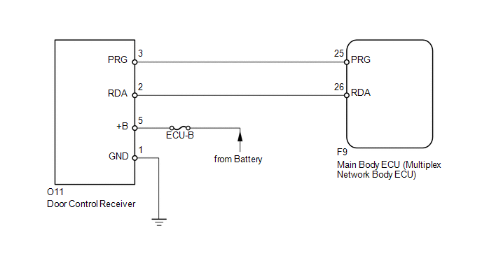
The door control receiver receives signals from the transmitter and sends these signals to the main body ECU. This DTC is stored when the applicable RDA signal cannot be received within 1 second of the PRG signal being output from the main body ECU.
|
DTC Code |
DTC Detection Condition |
Trouble Area |
|---|---|---|
|
B1242 |
The applicable RDA signal cannot be received within 1 second of the PRG signal being output from the main body ECU. |
|
WIRING DIAGRAM
CAUTION / NOTICE / HINT
NOTICE:
- Inspect the fuses for circuits related to this system before performing the following inspection procedure.
- When replacing the door control receiver, refer to the registration
procedures (See page
.gif) ).
).
PROCEDURE
|
1. |
CLEAR DTC |
(a) Clear the DTCs (See page ).
|
.gif)
|
2. |
CHECK FOR DTC |
(a) Check for DTCs (See page ).
OK:
DTC B1242 is not output.
| OK | .gif) |
USE SIMULATION METHOD TO CHECK |
|
|
3. |
CHECK DOOR CONTROL RECEIVER (DOOR CONTROL RECEIVER - MAIN BODY ECU) |
(a) Disconnect the O11 receiver connector.
(b) Disconnect the F9 ECU connector.
(c) Measure the resistance according to the value(s) in the table below.
Standard Resistance:
|
Tester Connection |
Condition |
Specified Condition |
|---|---|---|
|
O11-2 (RDA) - F9-26 (RDA) |
Always |
Below 1 Ω |
|
O11-3 (PRG) - F9-25 (PRG) |
||
|
O11-2 (RDA) or F9-26 (RDA) - Body ground |
Always |
10 kΩ or higher |
|
O11-3 (PRG) or F9-25 (PRG) - Body ground |
| NG | |
REPAIR OR REPLACE HARNESS OR CONNECTOR |
|
|
4. |
CHECK HARNESS AND CONNECTOR (DOOR CONTROL RECEIVER - BATTERY AND BODY GROUND) |
|
(a) Disconnect the O11 receiver connector. |
|
(b) Measure the resistance and voltage according to the value(s) in the table below.
Standard Resistance:
|
Tester Connection |
Condition |
Specified Condition |
|---|---|---|
|
O11-1 (GND) - Body ground |
Always |
Below 1 Ω |
Standard Voltage:
|
Tester Connection |
Condition |
Specified Condition |
|---|---|---|
|
O11-5 (+B) - Body ground |
Always |
11 to 14 V |
|
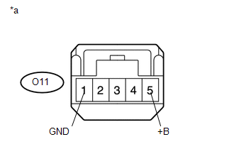
*a |
Front view of wire harness connector (to Door Control Receiver) |
| NG | |
REPAIR OR REPLACE HARNESS OR CONNECTOR |
|
|
5. |
REPLACE DOOR CONTROL RECEIVER |
(a) Temporarily replace the door control receiver with a new one (See page
).
(b) Perform the registration procedures (See page
).
|
|
6. |
CLEAR DTC |
(a) Clear the DTCs (See page ).
|
|
7. |
CHECK FOR DTC |
(a) Check for DTCs (See page ).
OK:
DTC B1242 is not output.
| OK | |
END (DOOR CONTROL RECEIVER IS DEFECTIVE) |
| NG | |
REPLACE MAIN BODY ECU (MULTIPLEX NETWORK BODY ECU) |
 Diagnostic Trouble Code Chart
DIAGNOSTIC TROUBLE CODE CHART
HINT:
If a trouble code is output during the DTC check, inspect the trouble areas listed
for that code. For details of the code, refer to the "See page" bel ...
 Only Wireless Control Function is Inoperative
DESCRIPTION
The door control receiver receives signals from the transmitter and sends these
signals to the main body ECU. The main body ECU then controls all the doors by sending
lock/unlock sign ...
Other materials about Toyota 4Runner:
Adjustment
ADJUSTMENT
CAUTION / NOTICE / HINT
HINT:
Centering bolts are used to mount the door hinge to the vehicle body
and door. The door cannot be adjusted with the centering bolts installed.
Substitute the centering bolts with standard bolts when ...
Front Blower Motor
Components
COMPONENTS
ILLUSTRATION
Removal
REMOVAL
PROCEDURE
1. REMOVE NO. 2 INSTRUMENT PANEL UNDER COVER SUB-ASSEMBLY
2. REMOVE BLOWER WITH FAN MOTOR SUB-ASSEMBLY
(a) Detach the clamp.
(b) Disconnect the connector.
(c) Remove the ...

0.0112