Toyota 4Runner: Open Circuit in IG1/IG2 Power Source Circuit (C1242)
DESCRIPTION
If there is a problem with the master cylinder solenoid (skid control ECU) power supply circuit, the skid control ECU stores DTCs and prohibits operation under the fail-safe function.
If the voltage supplied to the IG2 terminal is within the DTC detection range due to malfunctions in components such as the battery and generator circuit, this DTC is stored.
|
DTC Code |
DTC Detection Condition |
Trouble Area |
|---|---|---|
|
C1242 |
The vehicle speed is 3 km/h (1.9 mph) or more and the voltage at the ECU IG2 terminal remains below 6.5 V for more than 7 seconds. |
|
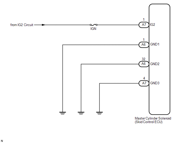
WIRING DIAGRAM
CAUTION / NOTICE / HINT
NOTICE:
- When replacing the master cylinder solenoid, perform calibration (See
page
.gif) ).
). - Inspect the fuses for circuits related to this system before performing the following inspection procedure.
PROCEDURE
|
1. |
CHECK TERMINAL VOLTAGE (IG2) |
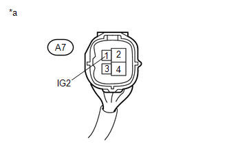
(a) Disconnect the A7 skid control ECU connector.
|
(b) Measure the voltage according to the value(s) in the table below. Standard Voltage:
|
|
| NG | .gif) |
REPAIR OR REPLACE HARNESS OR CONNECTOR |
|
.gif)
|
2. |
CHECK HARNESS AND CONNECTOR (GND1, GND2 AND GND3 TERMINAL) |
| NG | |
REPAIR OR REPLACE HARNESS OR CONNECTOR |
|
|
3. |
RECONFIRM DTC |
(a) Clear the DTCs (See page ).
(b) Turn the ignition switch off.
(c) Check if the same DTC is output (See page
).
HINT:
Reinstall the sensors, connectors, etc. and restore the previous vehicle conditions before rechecking for DTCs.
Result|
Result |
Proceed to |
|---|---|
|
DTC is output |
A |
|
DTC is not output |
B |
| A | |
REPLACE MASTER CYLINDER SOLENOID |
| B | |
USE SIMULATION METHOD TO CHECK |
 Low Power Supply Voltage Malfunction (C1241)
DESCRIPTION
If the voltage supplied to the IG1 terminal is within the DTC detection range
due to malfunctions in components such as the battery and generator circuit, this
DTC is stored.
...
 Open in Pump Motor Circuit (C1251)
DESCRIPTION
The motor relay (semiconductor relay) is built into the master cylinder solenoid
and drives the pump motor based on a signal from the skid control ECU.
DTC Code
D ...
Other materials about Toyota 4Runner:
Park / Neutral Position Switch Circuit
DESCRIPTION
This circuit sends the park/neutral position switch assembly signals to the clearance
warning ECU assembly.
WIRING DIAGRAM
CAUTION / NOTICE / HINT
NOTICE:
Inspect the fuses for circuits related to this system before performing the followin ...
Lifter Sensor Malfunction (B2653)
DESCRIPTION
When the front power seat switch LH does not receive a sensor signal despite
upward or downward movement of the seat by power seat motor operation, this DTC
is stored.
DTC Code
DTC Detection Condition
Trouble ...

0.0064