Toyota 4Runner: Open in ABS Solenoid Relay Circuit (C0278,C0279)
DESCRIPTION
The solenoid relay is built into the master cylinder solenoid.
This relay supplies power to each solenoid. If the initial check is OK, after the ignition switch is turned to ON, the relay turns on.
|
DTC Code |
DTC Detection Condition |
Trouble Area |
|---|---|---|
|
C0278 |
Either condition is met:
|
|
|
C0279 |
The following condition continues for at least 0.2 seconds.
|
WIRING DIAGRAM
Refer to DTCs C0226, C0236, C0246, C0256, C1225, C1226, C1227 and C1228 (See
page .gif) ).
).
CAUTION / NOTICE / HINT
NOTICE:
- When replacing the master cylinder solenoid, perform calibration (See
page ).
- Inspect the fuses for circuits related to this system before performing the following inspection procedure.
PROCEDURE
|
1. |
CHECK TERMINAL VOLTAGE (+BS) |
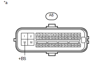
(a) Disconnect the A6 skid control ECU connector.
|
(b) Measure the voltage according to the value(s) in the table below. Standard Voltage:
|
|
| NG | .gif) |
REPAIR OR REPLACE HARNESS OR CONNECTOR |
|
.gif)
|
2. |
CHECK HARNESS AND CONNECTOR (GND1, GND2 AND GND3 TERMINAL) |
(a) Disconnect the A6 and A7 skid control ECU connectors.
(b) Measure the resistance according to the value(s) in the table below.
Standard Resistance:
|
Tester Connection |
Condition |
Specified Condition |
|---|---|---|
|
A6-1 (GND1) - Body ground |
Always |
Below 1 Ω |
|
A6-32 (GND2) - Body ground |
Always |
Below 1 Ω |
|
A7-4 (GND3) - Body ground |
Always |
Below 1 Ω |
| NG | |
REPAIR OR REPLACE HARNESS OR CONNECTOR |
|
|
3. |
RECONFIRM DTC |
HINT:
These codes are stored when a problem is detected in the master cylinder solenoid.
The solenoid relay is in the master cylinder solenoid.
Therefore, solenoid relay circuit inspections and relay unit inspections cannot be performed. Be sure to check if any DTC is output before replacing the master cylinder solenoid.
(a) Clear the DTCs (See page ).
(b) Drive the vehicle at a speed of approximately 32 km/h (20 mph) or more for 60 seconds or more.
(c) Check if the same DTCs are output (See page
).
HINT:
Reinstall the sensors, connectors, etc. and restore the previous vehicle conditions before rechecking for DTCs.
Result|
Result |
Proceed to |
|---|---|
|
DTC is output |
A |
|
DTC is not output |
B |
| A | |
REPLACE MASTER CYLINDER SOLENOID |
| B | |
USE SIMULATION METHOD TO CHECK |
 SFR Solenoid Circuit (C0226,C0236,C0246,C0256,C1225-C1228)
DESCRIPTION
The solenoid turns on when signals are received from the skid control ECU and
controls the pressure acting on the wheel cylinders, thus controlling braking force.
DTC Code
...
 ECM Communication Circuit Malfunction (C1203)
DESCRIPTION
The circuit is used to send control information from the skid control ECU to
the ECM, and engine control information from the ECM to the skid control ECU via
the CAN communication sys ...
Other materials about Toyota 4Runner:
Transfer Case Front Oil Seal
Components
COMPONENTS
ILLUSTRATION
Replacement
REPLACEMENT
PROCEDURE
1. DRAIN TRANSFER OIL
2. REMOVE FRONT PROPELLER SHAFT ASSEMBLY
(a) Remove the front propeller shaft (See page
).
3. REMOVE FRONT OUTPUT SHAFT COMPANION FLANGE SUB-ASSEMBLY ...
Installation
INSTALLATION
CAUTION / NOTICE / HINT
CAUTION:
Wear protective gloves. Sharp areas on the parts may injure your hands.
HINT:
Use the same procedure for the power seat RH and power seat LH sides.
The procedure listed below is for the power se ...

0.0089