Toyota 4Runner: Short to GND in Immobiliser System Power Source Circuit (B278A)
DESCRIPTION
This DTC is stored when the engine switch power source supply line is open or shorted.
|
DTC Code |
DTC Detection Condition |
Trouble Area |
|---|---|---|
|
B278A |
The engine switch power source supply line is open or shorted. |
|
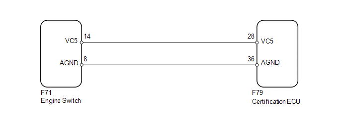
WIRING DIAGRAM
CAUTION / NOTICE / HINT
NOTICE:
Before replacing the certification ECU, refer to Registration (See page
.gif) ).
).
PROCEDURE
|
1. |
CHECK HARNESS AND CONNECTOR (CERTIFICATION ECU - ENGINE SWITCH) |
(a) Disconnect the F79 ECU connector.
(b) Disconnect the F71 switch connector.
(c) Measure the resistance according to the value(s) in the table below.
Standard Resistance:
|
Tester Connection |
Condition |
Specified Condition |
|---|---|---|
|
F79-28 (VC5) - F71-14 (VC5) |
Always |
Below 1 Ω |
|
F79-36 (AGND) - F71-8 (AGND) |
||
|
F79-28 (VC5) or F71-14 (VC5) - Body ground |
Always |
10 kΩ or higher |
|
F79-36 (AGND) or F71-8 (AGND) - Body ground |
| NG | .gif) |
REPAIR OR REPLACE HARNESS OR CONNECTOR |
|
.gif)
|
2. |
CHECK CERTIFICATION ECU |
|
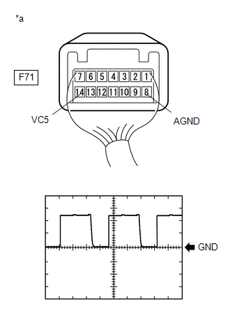
(a) Using an oscilloscope, check the waveform. Measurement Condition
OK: Waveform is output normally (refer to illustration). Text in Illustration
|
|
| OK | |
REPLACE ENGINE SWITCH |
| NG | |
REPLACE CERTIFICATION ECU |
 Theft Deterrent System Presence Detection (B279C)
DESCRIPTION
If an ECM that is incompatible with the engine immobiliser system is installed,
the ECM stores this DTC.
DTC Code
DTC Detection Condition
Trouble Area
...
 Antenna Coil Open / Short (B2784)
DESCRIPTION
This DTC is stored when there is an open or short malfunction in the transponder
key amplifier coil (built into the engine switch).
DTC Code
DTC Detection Conditi ...
Other materials about Toyota 4Runner:
Front Passenger Side Power Window does not Operate with Front Passenger Side
Power Window Switch
DESCRIPTION
If the manual up/down function does not operate, there may be a malfunction
in the power window regulator switch, front power window regulator motor,
harness or connector.
WIRING DIAGRAM
CAUTION / NOTICE / HINT
NOTICE:
I ...
How To Proceed With Troubleshooting
CAUTION / NOTICE / HINT
HINT:
Inspect the window defogger system after confirming that the back door
power window system of the power window control system is operating normally.
Use these procedures to troubleshoot the window defogger sys ...

0.0069