
Toyota 4Runner: Parts Location
Toyota 4Runner Service Manual / Vehicle Exterior / Window / Glass / Power Window Control System / Parts Location
PARTS LOCATION
ILLUSTRATION
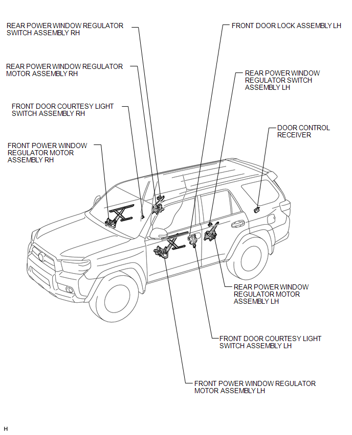
ILLUSTRATION
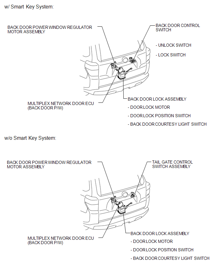
ILLUSTRATION
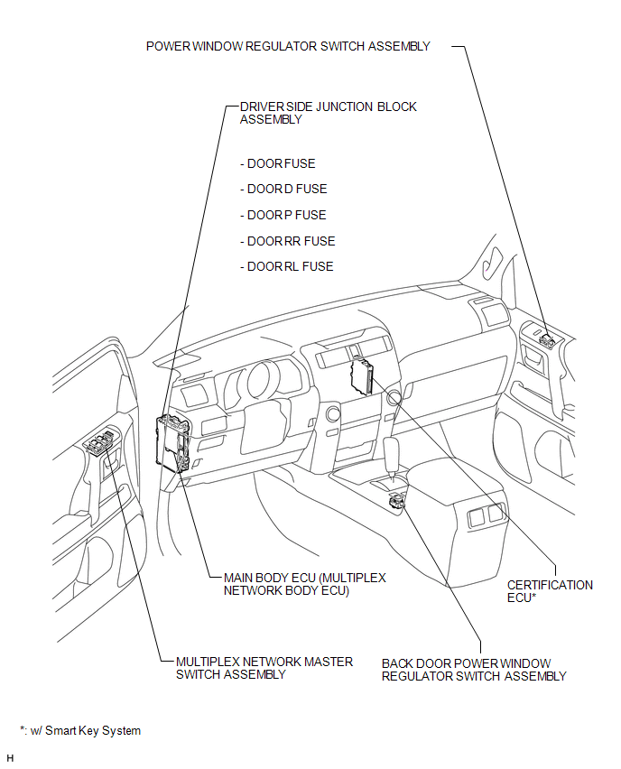
 Precaution
PRECAUTION
1. IGNITION SWITCH EXPRESSION
(a) The type of ignition switch used on this model differs depending on the specifications
of the vehicle. The expressions listed in the table below are us ...
 System Diagram
SYSTEM DIAGRAM
Communication Table
Transmitting ECU
Receiving ECU
Signal
Communication Method
Multiplex network master switch assemb ...
Other materials about Toyota 4Runner:
Steering Angle Sensor
Components
COMPONENTS
ILLUSTRATION
Removal
REMOVAL
PROCEDURE
1. PLACE FRONT WHEELS FACING STRAIGHT AHEAD
2. DISCONNECT CABLE FROM NEGATIVE BATTERY TERMINAL
CAUTION:
Wait at least 90 seconds after disconnecting the cable from the negative (-)
b ...
Stop Light Switch
Components
COMPONENTS
ILLUSTRATION
On-vehicle Inspection
ON-VEHICLE INSPECTION
PROCEDURE
1. INSPECT STOP LIGHT SWITCH ASSEMBLY
(a) Disconnect the connector from the stop light switch assembly.
...
© 2016-2026 | www.to4runner.net

0.0079
0.0079