Toyota 4Runner: System Diagram
SYSTEM DIAGRAM
 Communication Table
|
Transmitting ECU |
Receiving ECU |
Signal |
Communication Method |
|---|---|---|---|
|
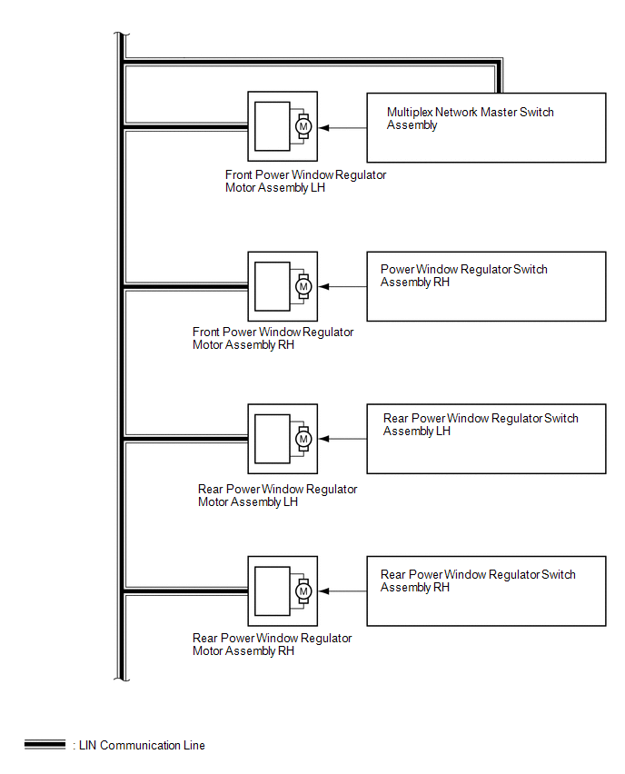
Multiplex network master switch assembly |
|
Power window auto up and down signal |
LIN |
|
Power window remote up and down signal |
LIN |
|
|
Main body ECU (Multiplex network body ECU) |
|
Power window operation permission signal |
LIN |
|
Main body ECU (Multiplex network body ECU) |
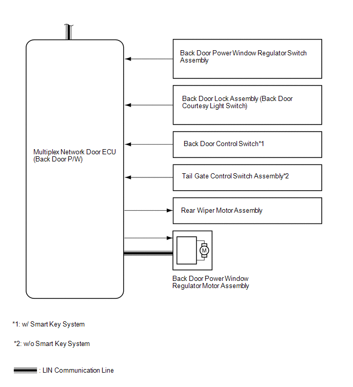
Multiplex network door ECU (Back door P/W) |
Back door power window operation permission signal |
LIN |
|
Multiplex network door ECU (Back door P/W) |
Main body ECU (Multiplex network body ECU) |
Power window position signal |
LIN |
|
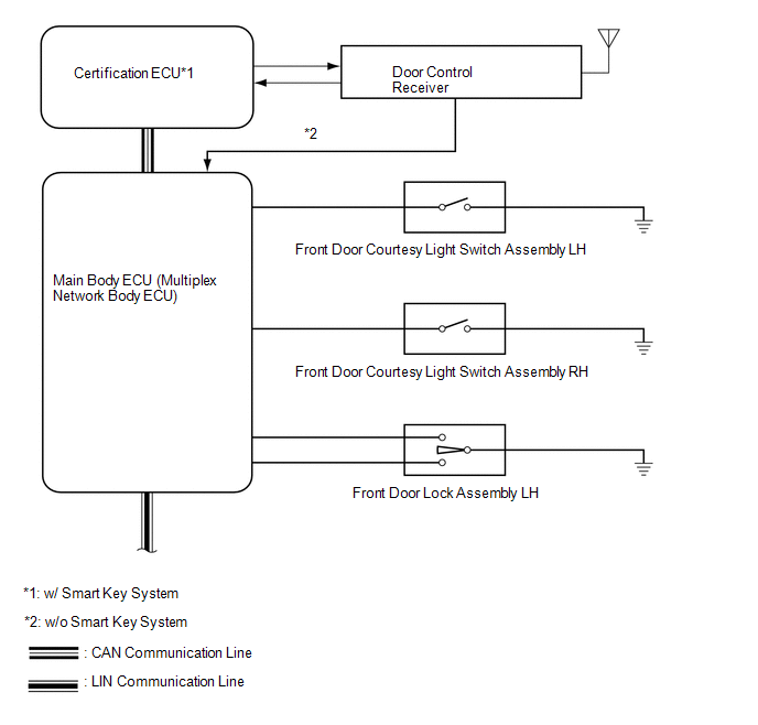
Certification ECU* |
Main body ECU (Multiplex network body ECU) |
Wireless power window up and down signal |
CAN |
- *: w/ Smart Key System
 Parts Location
PARTS LOCATION
ILLUSTRATION
ILLUSTRATION
ILLUSTRATION
...
 System Description
SYSTEM DESCRIPTION
1. POWER WINDOW CONTROL SYSTEM DESCRIPTION
(a) The power window control system controls the power window operation using
the power window regulator motors. The main controls of ...
Other materials about Toyota 4Runner:
Disc cannot be Inserted or is Ejected Right After Insertion
CAUTION / NOTICE / HINT
NOTICE:
After replacing the navigation receiver assembly of vehicles subscribed to pay-type
satellite radio broadcasts, XM radio ID registration is necessary.
PROCEDURE
1.
CHECK IF A PROPER DISC IS INSERTED
...
Torque Converter Clutch And Drive Plate
Inspection
INSPECTION
PROCEDURE
1. INSPECT TORQUE CONVERTER CLUTCH ASSEMBLY
(a) Inspect the 1-way clutch.
(1) Install SST to the inner race of the 1-way clutch.
SST: 09350-32014
09351-32020
(2) Press on the serrations of the starter with a finger a ...

0.025