Toyota 4Runner: Parts Location
Toyota 4Runner Service Manual / Vehicle Interior / Meter / Gauge / Display / Clock System / Parts Location
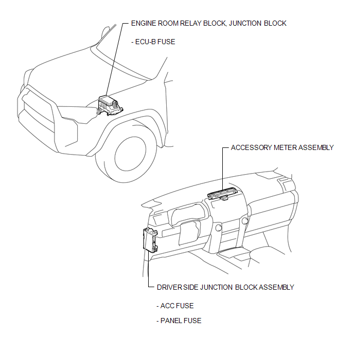
PARTS LOCATION
ILLUSTRATION
 Clock System
...
 System Diagram
SYSTEM DIAGRAM
1. POWER SOURCE CIRCUIT
...
Other materials about Toyota 4Runner:
Installation
INSTALLATION
CAUTION / NOTICE / HINT
HINT:
Use the same procedure for the RH and LH sides.
The procedure listed below is for the LH side.
When installing the window frame moulding, black out tape and outside
stripe, heat the vehicle body ...
How To Proceed With Troubleshooting
CAUTION / NOTICE / HINT
HINT:
Use these procedures to troubleshoot the rear view monitor system.
PROCEDURE
1.
VEHICLE BROUGHT TO WORKSHOP
NEXT
2.
...
© 2016-2026 | www.to4runner.net

0.0065
0.0065