Toyota 4Runner: Installation
INSTALLATION
PROCEDURE
1. INSTALL LOWER NO. 2 INSTRUMENT PANEL AIRBAG ASSEMBLY
|
(a) Connect the connector. NOTICE: When handling the airbag connector, take care not to damage the airbag wire harness. |
|
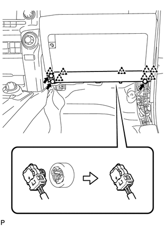
(b) Attach the 8 claws to install the instrument panel airbag.
(c) Install the 3 bolts.
Torque:
10 N·m {102 kgf·cm, 7 ft·lbf}
2. INSTALL LOWER INSTRUMENT COVER LH
.gif)
3. INSTALL FRONT NO. 2 CONSOLE BOX INSERT
4. INSTALL NO. 2 INSTRUMENT PANEL UNDER COVER SUB-ASSEMBLY
5. INSTALL NO. 2 INSTRUMENT CLUSTER FINISH PANEL GARNISH
6. INSTALL COWL SIDE TRIM BOARD RH
7. INSTALL DOOR SCUFF PLATE ASSEMBLY RH
HINT:
Use the same procedure as for the LH side (See page
).
8. CONNECT CABLE TO NEGATIVE BATTERY TERMINAL
NOTICE:
When disconnecting the cable, some systems need to be initialized after the cable
is reconnected (See page ).
9. CHECK SRS WARNING LIGHT
(a) Check the SRS warning light (See page ).
 Components
COMPONENTS
ILLUSTRATION
...
 On-vehicle Inspection
ON-VEHICLE INSPECTION
PROCEDURE
1. CHECK LOWER NO. 2 INSTRUMENT PANEL AIRBAG ASSEMBLY (VEHICLE NOT INVOLVED IN
COLLISION)
(a) Perform a diagnostic system check (See page
).
(b) With the lower ...
Other materials about Toyota 4Runner:
Capacity and distribution
Cargo capacity depends on the total weight of the occupants.
(Cargo capacity) = (Total load capacity) — (Total weight of occupants) Steps
for Determining Correct Load Limit-- (1)Locate the statement “The combined
weight of occupants and cargo should n ...
Using the audio control function
Changing sound quality modes
Type A
Pressing selects the mode to be
changed in the following order:
“BAS”→“TRE”→“FAD”→“BAL”→“ASL”
Type B and C Press
.
Press
,
,
,
or
(type C only) as corresponds to
the desired mod ...

0.0066