Toyota 4Runner: System Diagram
Toyota 4Runner Service Manual / Vehicle Interior / Meter / Gauge / Display / Clock System / System Diagram
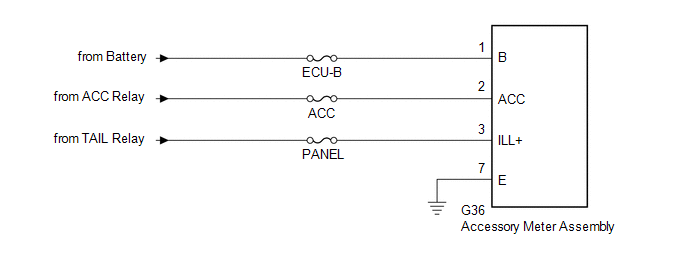
SYSTEM DIAGRAM
1. POWER SOURCE CIRCUIT
 Parts Location
PARTS LOCATION
ILLUSTRATION
...
 How To Proceed With Troubleshooting
CAUTION / NOTICE / HINT
Use these procedures to troubleshoot the clock system.
PROCEDURE
1.
VEHICLE BROUGHT TO WORKSHOP
NEXT
...
Other materials about Toyota 4Runner:
Dcm Power Source Circuit
DESCRIPTION
This is the power source circuit to operate the DCM (Telematics Transceiver).
WIRING DIAGRAM
CAUTION / NOTICE / HINT
NOTICE:
Inspect the fuses for circuits related to this system before performing the following
inspection procedure.
PROCE ...
Rear Shock Absorber(w/ Reas)
Components
COMPONENTS
ILLUSTRATION
Removal
REMOVAL
CAUTION / NOTICE / HINT
NOTICE:
Be sure to read the precaution before performing this procedure (See page
).
HINT:
Use the same procedure for the RH and LH sides.
The procedure lis ...
© 2016-2026 | www.to4runner.net

0.0266
0.0266