Toyota 4Runner: Parts Location
Toyota 4Runner Service Manual / Audio / Visual / Telematics / Audio / Video / Audio And Visual System / Parts Location
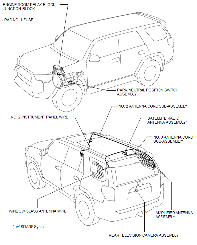
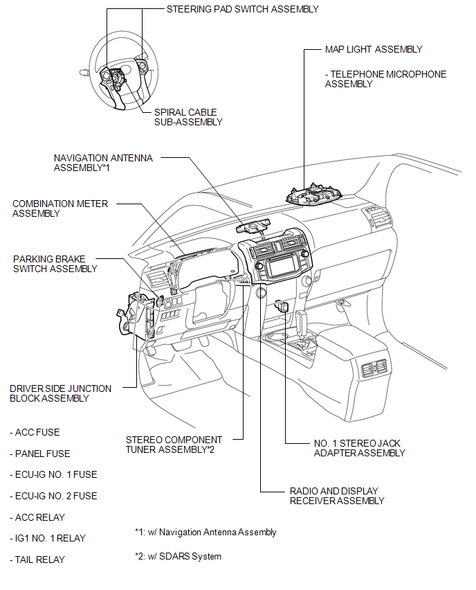
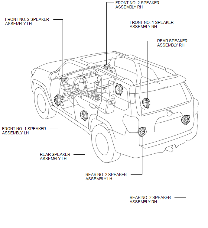
PARTS LOCATION
ILLUSTRATION
ILLUSTRATION
ILLUSTRATION
 Precaution
PRECAUTION
1. IGNITION SWITCH EXPRESSIONS
(a) The type of ignition switch used on this model differs depending on the specifications
of the vehicle. The expressions listed in the table below are u ...
 System Diagram
SYSTEM DIAGRAM
...
Other materials about Toyota 4Runner:
Front Passenger Side Power Window Switch
Components
COMPONENTS
ILLUSTRATION
Inspection
INSPECTION
PROCEDURE
1. INSPECT POWER WINDOW REGULATOR SWITCH ASSEMBLY
(a) Measure the resistance according to the value(s) in the table below.
Standard Resistance:
T ...
Problem Symptoms Table
PROBLEM SYMPTOMS TABLE
HINT:
Use the table below to help determine the cause of problem symptoms.
If multiple suspected areas are listed, the potential causes of the symptoms
are listed in order of probability in the "Suspected Area" ...
© 2016-2026 | www.to4runner.net

0.0074
0.0074