Toyota 4Runner: Parts Location
Toyota 4Runner Service Manual / Power Source / Network / Networking / Can Communication System / Parts Location
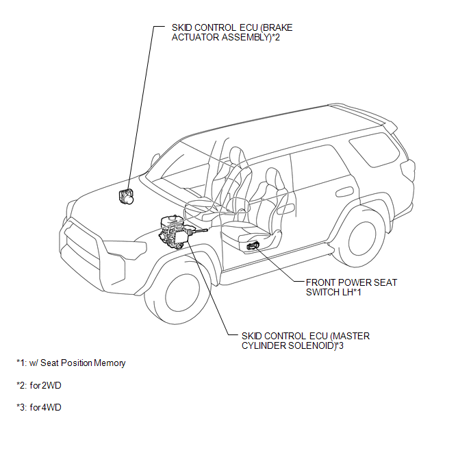
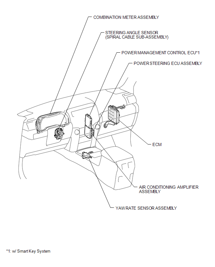
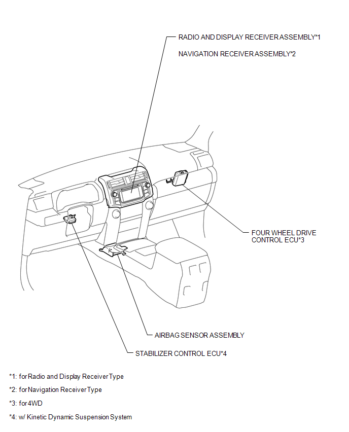
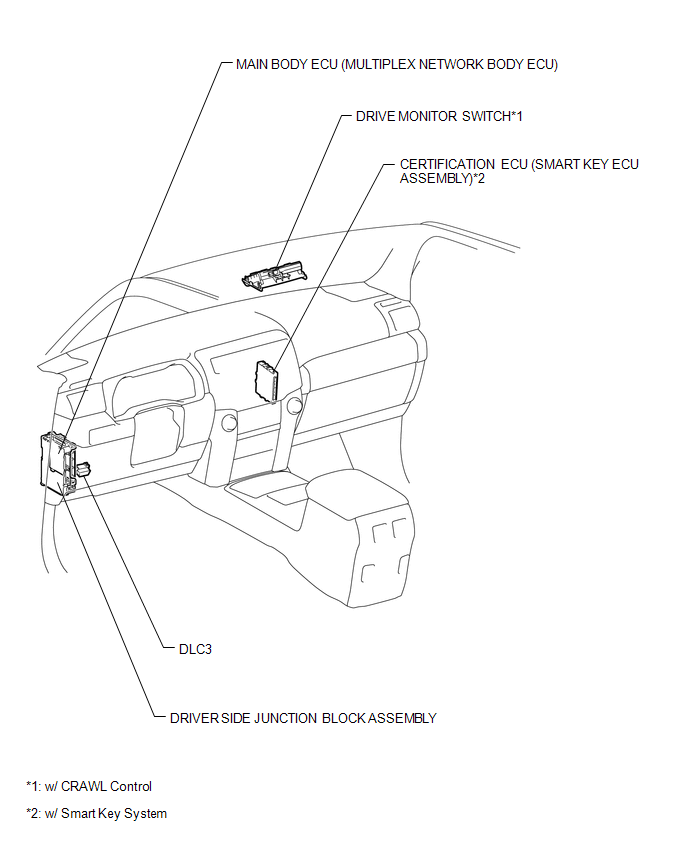
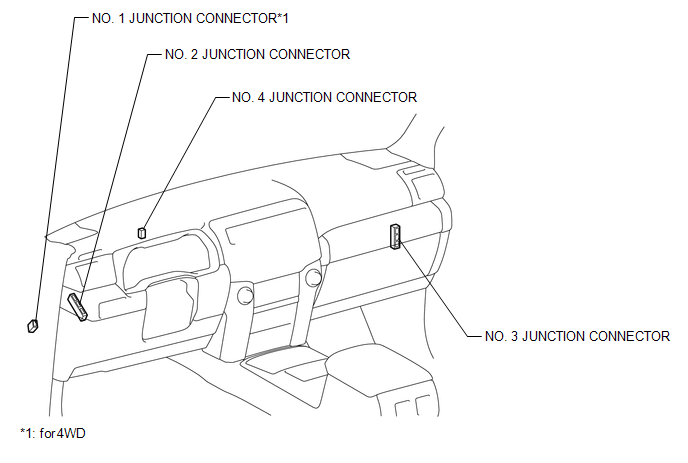
PARTS LOCATION
ILLUSTRATION
ILLUSTRATION
ILLUSTRATION
ILLUSTRATION
ILLUSTRATION
 Precaution
PRECAUTION
1. IGNITION SWITCH EXPRESSION
HINT:
The type of ignition switch used on this model differs according to the specifications
of the vehicle. The expressions listed in the table below are ...
 System Description
SYSTEM DESCRIPTION
1. BRIEF DESCRIPTION
(a) The CAN (Controller Area Network) is a serial data communication system for
real-time application. It is a vehicle multiplex communication system which ...
Other materials about Toyota 4Runner:
Downhill Assist Control Indicator Light Remains ON
DESCRIPTION
When the downhill assist control switch is turned on, the downhill assist control
function is available and the downhill assist control indicator light illuminates.
WIRING DIAGRAM
Refer to Downhill Assist Control Indicator Light does not Come ...
Operation Check
OPERATION CHECK
1. AUTOMATIC LIGHT CONTROL SYSTEM OPERATION CHECK
(a) Turn the ignition switch to ON.
(b) Turn the headlight dimmer switch to the AUTO position.
(c) Cover the automatic light control sensor.
(d) Check that the taillights and low beam headl ...
© 2016-2026 | www.to4runner.net

0.0275
0.0275