Toyota 4Runner: Power Source Mode does not Change to ON (IG and ACC)
DESCRIPTION
When the engine switch is pushed with the key in the cabin, the power management control receives signals to switch the power source mode.
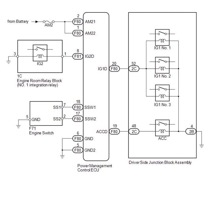
WIRING DIAGRAM
CAUTION / NOTICE / HINT
NOTICE:
- When using the Techstream with the engine switch off to troubleshoot: Connect the Techstream to the vehicle and turn a courtesy light switch on and off at 1.5 second intervals until communication between the Techstream and vehicle begins.
- Before performing the inspection, check that there are no problems related to the CAN communication system and LIN communication system.
- Inspect the fuses for circuits related to this system before performing the following inspection procedure.
PROCEDURE
|
1. |
CHECK HARNESS AND CONNECTOR (BATTERY - POWER MANAGEMENT CONTROL ECU) |
.gif)
| NG | .gif) |
REPAIR OR REPLACE HARNESS OR CONNECTOR |
|
.gif)
|
2. |
CHECK HARNESS AND CONNECTOR (POWER MANAGEMENT CONTROL ECU - BODY GROUND) |
| NG | |
REPAIR OR REPLACE HARNESS OR CONNECTOR |
|
|
3. |
READ VALUE USING TECHSTREAM (KEY CERTIFI WAIT T-OUT) |
(a) Connect the Techstream to the DLC3.
(b) Turn the Techstream on.
HINT:
When using the Techstream with the engine switch off, turn any of the door courtesy light switches on and off repeatedly at intervals of 1.5 seconds or less until communication between the tester and vehicle starts.
(c) Enter the following menus: Body Electrical / Power Source Control / Data List.
(d) Read the Data List and check that "No" is displayed 1 second after turning the engine switch from off to on (IG).
Power Source Control|
Tester Display |
Measurement Item/Range |
Normal Condition |
Diagnostic Note |
|---|---|---|---|
|
Key Certifi Wait T-Out |
Key certification waiting timed out / Yes or No |
Yes: Key certification waiting timed out No: Key certification completed within specified time |
- |
OK:
"No" is displayed 1 second after turning the engine switch from off to on (IG).
| NG | |
GO TO STEP 9 |
|
|
4. |
READ VALUE USING TECHSTREAM (START SWITCH 1, 2) |
(a) Connect the Techstream to the DLC3.
(b) Turn the engine switch on (IG).
(c) Turn the Techstream on.
(d) Enter the following menus: Body Electrical / Power Source Control / Data List.
(e) According to the display on the Techstream, read the Data List.
Power Source Control|
Tester Display |
Measurement Item/Range |
Normal Condition |
Diagnostic Note |
|---|---|---|---|
|
Start Switch1 |
Start Switch 1 / ON or OFF |
ON: Engine switch pushed OFF: Engine switch not pushed |
- |
|
Start Switch2 |
Start Switch 2 / ON or OFF |
ON: Engine switch pushed OFF: Engine switch not pushed |
- |
OK:
The display changes in response to the operation of the engine switch.
| NG | |
GO TO STEP 7 |
|
|
5. |
CHECK POWER MANAGEMENT CONTROL ECU |
(a) Connect the Techstream to the DLC3.
(b) Turn the engine switch on (IG).
(c) Turn the Techstream on.
(d) Enter the following menus: Body Electrical / Power Source Control / Data List.
(e) Read the Data List and check that the display changes according to the changes in the power source mode when the engine switch is pushed.
Power Source Control|
Tester Display |
Measurement Item/Range |
Normal Condition |
Diagnostic Note |
|---|---|---|---|
|
Power Supply Condition |
Power Supply Condition / IG2 ON, ST ON, All OFF, IG1 ON or ACC ON |
IG2 ON: IG2 relay on ST ON: ST request signal on All OFF: All relays off IG1 ON: IG1 relay on ACC ON: ACC relay on |
- |
OK:
Display changes according to the changes in the power source mode when the engine switch is pushed.
(f) Measure the voltage according to the value(s) in the table below.
 Text in Illustration
|
*a |
Component with harness connected (Power Management Control ECU) |
- |
- |
Standard Voltage:
|
Tester Connection |
Switch Condition |
Specified Condition |
|---|---|---|
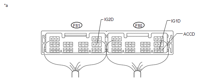
|
F80-20 (IG1D) - Body ground |
Engine switch off |
Below 1 V |
|
Engine switch on (ACC) |
||
|
Engine switch on (IG) |
((Voltage at terminal AM21 or AM22) minus 2.0 V) or higher |
|
|
F81-8 (IG2D) - Body ground |
Engine switch off |
Below 1 V |
|
Engine switch on (ACC) |
||
|
Engine switch on (IG) |
((Voltage at terminal AM21 or AM22) minus 2.0 V) or higher |
|
|
F80-19 (ACCD) - Body ground |
Engine switch off |
Below 1 V |
|
Engine switch on (ACC) |
((Voltage at terminal AM21 or AM22) minus 2.0 V) or higher |
|
|
Engine switch on (IG) |
((Voltage at terminal AM21 or AM22) minus 2.0 V) or higher |
| NG | |
REPLACE POWER MANAGEMENT CONTROL ECU |
|
|
6. |
CONFIRMATION TEST |
(a) Check that the power source mode changes to on (ACC) and on (IG) when operating the engine switch.
OK:
The power source mode changes to on (ACC) and on (IG) in response to the operation of the engine switch.
| OK | |
USE SIMULATION METHOD TO CHECK |
| NG | |
CHECK RELAY CONTACT SIDE CIRCUIT |
|
7. |
INSPECT ENGINE SWITCH |
|
(a) Remove the engine switch. |
|
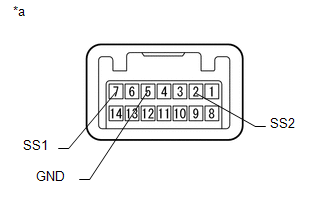
(b) Measure the resistance according to the value(s) in the table below.
Standard Resistance:
|
Tester Connection |
Switch Condition |
Specified Condition |
|---|---|---|
|
7 (SS1) - 5 (GND) |
Engine switch not pushed |
10 kΩ or higher |
|
Engine switch pushed |
Below 1 Ω |
|
|
2 (SS2) - 5 (GND) |
Engine switch not pushed |
10 kΩ or higher |
|
Engine switch pushed |
Below 1 Ω |
|
*a |
Component without harness connected (Engine Switch) |
| NG | |
REPLACE ENGINE SWITCH |
|
|
8. |
CHECK HARNESS AND CONNECTOR (POWER MANAGEMENT CONTROL ECU - ENGINE SWITCH) |
(a) Disconnect the F80 power management control ECU connector.
(b) Disconnect the F71 engine switch connector.
(c) Measure the resistance according to the value(s) in the table below.
Standard Resistance:
|
Tester Connection |
Condition |
Specified Condition |
|---|---|---|
|
F80-17 (SSW2) - F71-2 (SS2) |
Always |
Below 1 Ω |
|
F80-18 (SSW1) - F71-7 (SS1) |
||
|
F80-17 (SSW2) - Body ground |
Always |
10 kΩ or higher |
|
F80-18 (SSW1) - Body ground |
||
|
F71-5 (GND) - Body ground |
Always |
Below 1 Ω |
| OK | |
REPLACE POWER MANAGEMENT CONTROL ECU |
| NG | |
REPAIR OR REPLACE HARNESS OR CONNECTOR |
|
9. |
CHECK FOR DTC |
(a) Connect the Techstream to the DLC3.
(b) Turn the engine switch on (IG).
(c) Turn the Techstream on.
(d) Enter the following menus: Body Electrical / Power Source / Trouble Codes.
(e) Read the DTCs.
(f) Enter the following menus: Body Electrical / Smart Key / Trouble Codes.
(g) Read the DTCs.
Result|
Result |
Proceed to |
|---|---|
|
None of the following DTCs are output: B2785 Communication Malfunction between ECUs Connected by LIN B2287 LIN Communication Master Malfunction B2784 Antenna Coil Open/Short |
A |
|
DTC B2287 is output but B2785 is not output. |
B |
|
A DTC other than B2287 is output. |
C |
| A | |
GO TO SMART KEY SYSTEM (FOR ENTRY FUNCTION) (Room Oscillator does not Recognize Key) |
| B | |
GO TO DTC (B2287) |
| C | |
GO TO DTC CHART |
 Engine does not Start
DESCRIPTION
The push-button start function uses a push-type engine switch, which the driver
can operate by merely carrying the key. This system consists primarily of the power
management control ...
 Power Source Mode does not Change to ON (IG)
DESCRIPTION
When the engine switch is pushed with the key in the cabin, the power management
control ECU receives signals to switch the power source mode.
WIRING DIAGRAM
Refer to "Power Sour ...
Other materials about Toyota 4Runner:
Precaution
PRECAUTION
1. IGNITION SWITCH EXPRESSION
HINT:
The type of ignition switch used on this model differs depending on the specifications
of the vehicle. The expressions listed in the table below are used in this section.
Expression
Ign ...
Diagnostic Trouble Code Chart
DIAGNOSTIC TROUBLE CODE CHART
NOTICE:
Turn the ignition switch off before removing parts.
HINT:
If no abnormality is found when inspecting parts, inspect the stabilizer
control ECU and ground points for poor contact.
If a trouble code is ou ...

0.007