Toyota 4Runner: Power Window Master Switch
Components
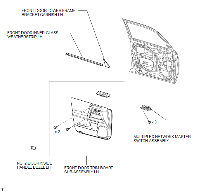
COMPONENTS
ILLUSTRATION
Removal
REMOVAL
PROCEDURE
1. REMOVE FRONT DOOR LOWER FRAME BRACKET GARNISH LH
.gif)
2. REMOVE NO. 2 DOOR INSIDE HANDLE BEZEL LH
3. REMOVE FRONT DOOR TRIM BOARD SUB-ASSEMBLY LH
4. REMOVE FRONT DOOR INNER GLASS WEATHERSTRIP LH
5. REMOVE MULTIPLEX NETWORK MASTER SWITCH ASSEMBLY
|
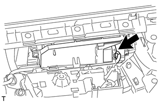
(a) Disconnect the connector. |
|
|
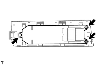
(b) Detach the 10 claws from the backside and remove the multiplex network master switch with base panel. |
|
|
(c) Remove the 3 screws and multiplex network master switch assembly. |
|
Inspection
INSPECTION
PROCEDURE
1. INSPECT MULTIPLEX NETWORK MASTER SWITCH ASSEMBLY
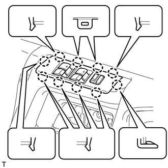
(a) Check that the LED illuminates.
(1) Apply battery voltage to the master switch and check that the LEDs illuminate.
OK:
|
Measurement Condition |
Specified Condition |
|---|---|
|
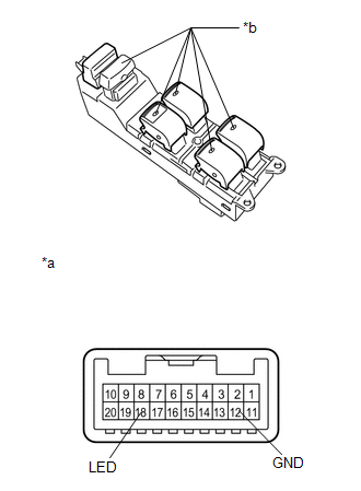
Battery positive (+) → 18 (LED) Battery negative (-) → 12 (GND) |
LEDs illuminate |
- If the result is not as specified, replace the multiplex network master switch assembly.
|
*a |
Component without harness connected (Multiplex Network Master Switch Assembly) |
|
*b |
LED |
Installation
INSTALLATION
PROCEDURE
1. INSTALL MULTIPLEX NETWORK MASTER SWITCH ASSEMBLY
(a) Install the multiplex network master switch assembly with the 3 screws.
(b) Attach the 10 claws to install the multiplex network master switch with base panel.
(c) Connect the connector.
2. INSTALL FRONT DOOR INNER GLASS WEATHERSTRIP LH
.gif)
3. INSTALL FRONT DOOR TRIM BOARD SUB-ASSEMBLY LH
4. INSTALL NO. 2 DOOR INSIDE HANDLE BEZEL LH
5. INSTALL FRONT DOOR LOWER FRAME BRACKET GARNISH LH
6. INSTALL NO. 2 DOOR INSIDE HANDLE BEZEL LH
 Jam Protection Function does not Operate
DESCRIPTION
This problem may occur in all door windows.
The jam protection function operates within a specified range during
the manual up or auto up operation.
PROCEDURE
...

Other materials about Toyota 4Runner:
How To Proceed With Troubleshooting
CAUTION / NOTICE / HINT
HINT:
*: Use the Techstream.
PROCEDURE
1.
VEHICLE BROUGHT TO WORKSHOP
NEXT
2.
CUSTOMER PROBLEM ANALYSIS
...
Suspension Control System(w/ Reas)
Precaution
PRECAUTION
1. HANDLING PRECAUTIONS FOR CENTER UNIT AND SHOCK ABSORBER
(a) Replacement of each unit is allowed if there is no fluid leakage. However,
in the case of fluid leakage from the system, replace both the absorber and center
unit as ...

0.0223