Toyota 4Runner: Ptc Heater Assembly
Components
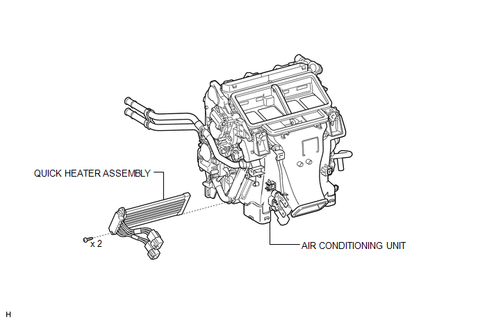
COMPONENTS
ILLUSTRATION
Removal
REMOVAL
PROCEDURE
1. REMOVE AIR CONDITIONING UNIT
(a) Remove the air conditioning unit (See page
.gif) ).
).
2. REMOVE QUICK HEATER ASSEMBLY
|
(a) Detach the 2 clamps. |
|
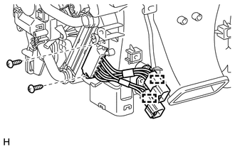
(b) Remove the 2 screws and quick heater.
Inspection
INSPECTION
PROCEDURE
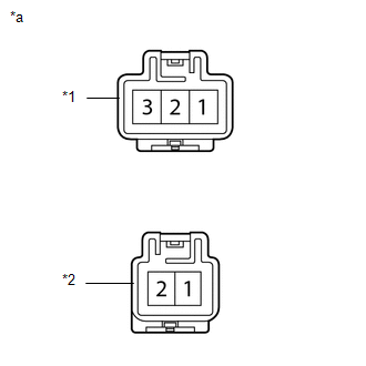
1. INSPECT QUICK HEATER ASSEMBLY
|
(a) Measure the resistance according to the value(s) in the table below. Standard Resistance:
|
|
Installation
INSTALLATION
PROCEDURE
1. INSTALL QUICK HEATER ASSEMBLY
(a) Attach the 2 clamps to install the quick heater.
(b) Install the 2 screws.
2. INSTALL AIR CONDITIONING UNIT
(a) Install the air conditioning unit (See page
.gif) ).
).
 Reassembly
REASSEMBLY
PROCEDURE
1. INSTALL NO. 1 COOLER THERMISTOR
NOTICE:
If reusing the evaporator, do not insert the sensor into a location where the
sensor was previously inserted.
(a) Insert the se ...
 Refrigerant
...
Other materials about Toyota 4Runner:
Installation
INSTALLATION
CAUTION / NOTICE / HINT
HINT:
Use the same procedure for the RH and LH sides.
The procedure listed below is for the LH side.
A bolt without a torque specification is shown in the standard bolt
chart (See page ).
PROC ...
Terminals Of Ecu
TERMINALS OF ECU
Text in Illustration
*a
Component with harness connected
(Stabilizer Control ECU)
-
-
Terminal No.
(Symbol)
Wiring Color
Terminal Description
...

0.0265