Toyota 4Runner: Reassembly
REASSEMBLY
PROCEDURE
1. INSTALL NO. 1 COOLER THERMISTOR
.png)
NOTICE:
If reusing the evaporator, do not insert the sensor into a location where the sensor was previously inserted.
(a) Insert the sensor to a location that is 1 fin to the right or left of its previous location.
Standard:
|
Item |
Specified Condition |
|---|---|
|
a |
50 mm (1.97 in.) |
|
b |
46.7 mm (1.84 in.) |
|
c |
33.3 mm (1.31 in.) |
|
d |
154.1 mm (6.07 in.) |
|
e |
25 mm (0.98 in.) |
|
*1 |
1 Fin |
2. INSTALL NO. 1 COOLER EVAPORATOR SUB-ASSEMBLY
(a) Sufficiently apply compressor oil to 2 new O-rings and the fitting surface of the hose joint.
Compressor oil:
ND-OIL 8 or equivalent
(b) Install the 2 O-rings to the evaporator.
|
(c) Install the evaporator. |
|
.png)
(d) Attach the 4 claws to install the unit case.
(e) Install the 6 screws.
3. INSTALL DAMPER SERVO SUB-ASSEMBLY LH
(a) Align the grooves on the damper servo sub-assembly with the protrusions on the unit and install the damper servo sub-assembly.
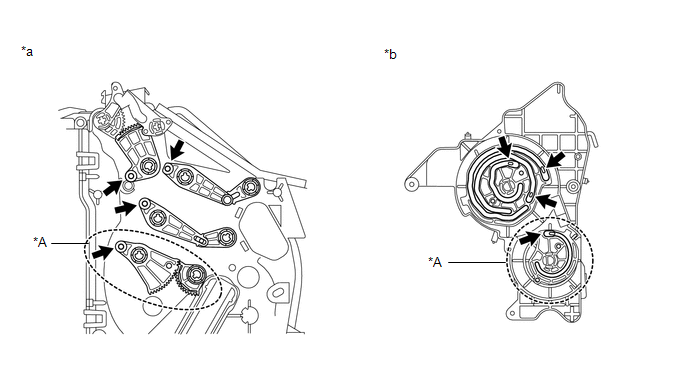 Text in Illustration
|
*A |
for Automatic Air Conditioning System |
- |
- |
|
*a |
Air Conditioning Unit Side |
*b |
Damper Servo Side |
(b) Install the 4 screws.
4. INSTALL DAMPER SERVO SUB-ASSEMBLY RH
(a) Align the grooves on the damper servo sub-assembly with the protrusions on the unit and install the damper servo sub-assembly.
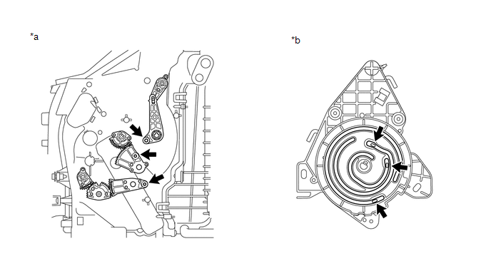 Text in Illustration
|
*a |
Air Conditioning Unit Side |
*b |
Damper Servo Side |
(b) Install the 3 screws.
5. INSTALL COOLER EXPANSION VALVE
(a) Install the expansion valve.
6. INSTALL AIR CONDITIONING TUBE AND ACCESSORY ASSEMBLY
(a) Sufficiently apply compressor oil to 2 new O-rings and the fitting surface of the hose joint.
Compressor oil:
ND-OIL 8 or equivalent
(b) Install the 2 O-rings to the air conditioning tube and accessory assembly.
(c) Install the air conditioning tube and accessory assembly.
(d) Using a 4 mm hexagon wrench, install the 2 hexagon bolts.
Torque:
3.5 N·m {36 kgf·cm, 31 in·lbf}
(e) Install new butyl tape.
(f) Install new packing.
7. INSTALL AIR CONDITIONING HARNESS
(a) Attach the clamps to install the harness.
(b) Connect the connectors.
8. INSTALL HEATER RADIATOR UNIT SUB-ASSEMBLY
(a) Install the radiator.
(b) Install the bracket with the 2 screws.
9. INSTALL QUICK HEATER ASSEMBLY (w/ PTC Heater)
.gif)
10. INSTALL DRAIN COOLER HOSE
|
(a) Install the drain cooler hose as shown in the illustration. |
|
.png)
11. INSTALL ASPIRATOR HOSE
(a) Attach the 2 claws to install the aspirator hose.
12. INSTALL DEFROSTER NOZZLE ASSEMBLY
(a) Attach the 6 claws to install the defroster nozzle assembly.
13. INSTALL BLOWER ASSEMBLY
(a) Attach the 2 claws to install the blower assembly.
(b) Install the screw.
Torque:
2.7 N·m {28 kgf·cm, 24 in·lbf}
 Installation
INSTALLATION
PROCEDURE
1. INSTALL AIR CONDITIONING UNIT
(a) Install the air conditioning unit (See page
).
...
 Ptc Heater Assembly
Components
COMPONENTS
ILLUSTRATION
Removal
REMOVAL
PROCEDURE
1. REMOVE AIR CONDITIONING UNIT
(a) Remove the air conditioning unit (See page
).
2. REMOVE QUICK HEATER ASSEMBLY
...
Other materials about Toyota 4Runner:
Installation with LATCH system (rear/second row seats only)
Installing on the rear seats (vehicles without third row seats)
Fold the seatback while pulling the seatback angle adjustment lever. Return
the seatback and secure it at the first lock position.
Type A
Latch the hooks of the lower straps onto the LATC ...
Lost Communication with Gateway Module (MS Bus) (U1002,U1114)
DESCRIPTION
The main body ECU (multiplex network body ECU) stores this DTC when
no signals can be received from the ECUs that are memorized as those connected
to the CAN MS bus.
When the main body ECU (multiplex network body ECU) receives a ...

0.0073