Toyota 4Runner: Push Switch / Key Unlock Warning Switch Malfunction (B2780)
DESCRIPTION
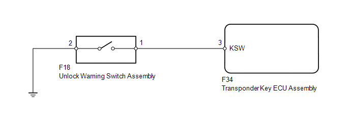
This DTC is stored if the transponder key ECU assembly does not detect that the unlock warning switch assembly is on even when the ignition switch is ON. Under normal conditions, the unlock warning switch assembly is on when the ignition switch is ON.
|
DTC Code |
DTC Detection Condition |
Trouble Area |
|---|---|---|
|
B2780 |
The unlock warning switch assembly is not detected as being on when the ignition switch is ON. |
|
WIRING DIAGRAM
CAUTION / NOTICE / HINT
NOTICE:
When the transponder key ECU assembly is replaced, refer to Registration (See
page .gif) ).
).
PROCEDURE
|
1. |
CLEAR DTC |
(a) Clear the DTCs (See page ).
|
.gif)
|
2. |
CHECK FOR DTC |
(a) Check for DTCs (See page ).
OK:
DTC B2780 is not output.
| OK | .gif) |
USE SIMULATION METHOD TO CHECK |
|
|
3. |
INSPECT UNLOCK WARNING SWITCH ASSEMBLY |
|
(a) Remove the unlock warning switch assembly (See page
|
|
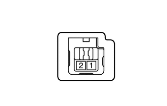
(b) Measure the resistance according to the value(s) in the table below.
Standard Resistance:
|
Tester Connection |
Switch Condition |
Specified Condition |
|---|---|---|
|
1 - 2 |
Pushed |
Below 1 Ω |
|
Not pushed |
10 kΩ or higher |
| NG | |
REPLACE UNLOCK WARNING SWITCH ASSEMBLY |
|
|
4. |
CHECK HARNESS AND CONNECTOR (UNLOCK WARNING SWITCH - TRANSPONDER KEY ECU AND BODY GROUND) |
(a) Disconnect the F18 switch connector.
(b) Disconnect the F34 ECU connector.
(c) Measure the resistance according to the value(s) in the table below.
Standard Resistance:
|
Tester Connection |
Condition |
Specified Condition |
|---|---|---|
|
F34-3 (KSW) - F18-1 |
Always |
Below 1 Ω |
|
F34-3 (KSW) or F18-1 - Body ground |
Always |
10 kΩ or higher |
|
F18-2 - Body ground |
Always |
Below 1 Ω |
| OK | |
REPLACE TRANSPONDER KEY ECU ASSEMBLY |
| NG | |
REPAIR OR REPLACE HARNESS OR CONNECTOR |
 Problem Symptoms Table
PROBLEM SYMPTOMS TABLE
HINT:
Use the table below to help determine the cause of problem symptoms.
If multiple suspected areas are listed, the potential causes of the symptoms
are lis ...
 Data List / Active Test
DATA LIST / ACTIVE TEST
1. READ DATA LIST
HINT:
Using the Techstream to read the Data List allows the values or states of switches,
sensors, actuators and other items to be read without removing ...
Other materials about Toyota 4Runner:
Inspection
INSPECTION
PROCEDURE
1. INSPECT VANE PUMP SHAFT AND BUSH IN VANE PUMP FRONT HOUSING
(a) Using a micrometer, measure the outer diameter of the vane pump shaft.
Text in Illustration
*a
Outer Diameter
...
Portable Player cannot be Registered
CAUTION / NOTICE / HINT
HINT:
Some versions of "Bluetooth" compatible audio players may not function, or the
function may be limited using the navigation receiver assembly, even if the portable
audio player itself can play files (See page ).
...

0.0257