Toyota 4Runner: Radio Receiver
Components
COMPONENTS
ILLUSTRATION
ILLUSTRATION
Removal
REMOVAL
PROCEDURE
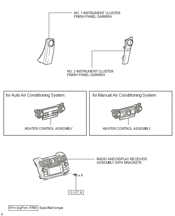
1. REMOVE NO. 1 INSTRUMENT CLUSTER FINISH PANEL GARNISH
.gif)
2. REMOVE NO. 2 INSTRUMENT CLUSTER FINISH PANEL GARNISH
3. REMOVE HEATER CONTROL ASSEMBLY
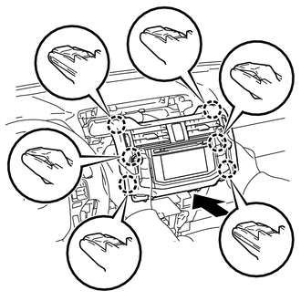
4. REMOVE RADIO AND DISPLAY RECEIVER ASSEMBLY WITH BRACKETS
|
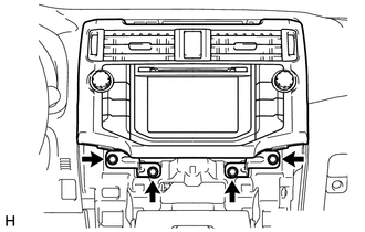
(a) Remove the 4 bolts. |
|
|
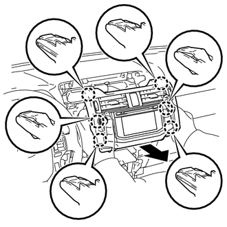
(b) Pull the radio and display receiver assembly with brackets as shown in the illustration to detach the 6 claws on the backside of the radio and display receiver assembly with brackets. |
|
|
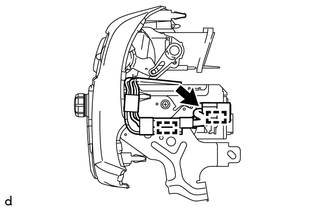
(c) Disconnect each connector to remove the radio and display receiver assembly with brackets. |
|
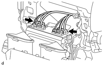
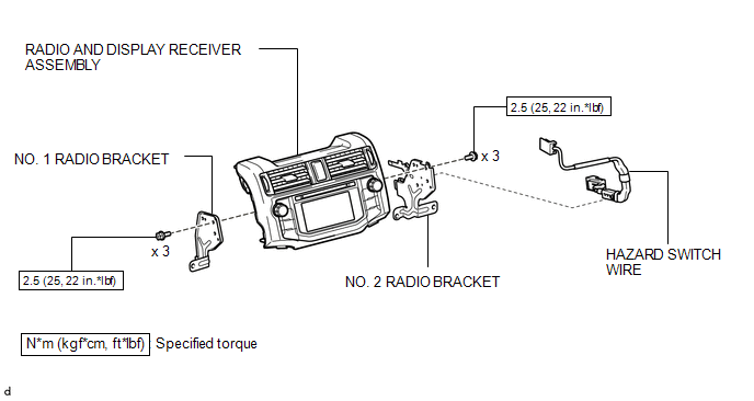
5. REMOVE HAZARD SWITCH WIRE
|
(a) Detach the 2 clamps. |
|
(b) Disconnect the connector to remove the hazard switch wire.
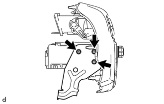
6. REMOVE NO. 1 RADIO BRACKET
|
(a) Remove the 3 screws and No. 1 radio bracket. |
|
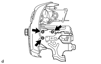
7. REMOVE NO. 2 RADIO BRACKET
|
(a) Remove the 3 screws and No. 2 radio bracket. |
|
Installation
INSTALLATION
PROCEDURE
1. INSTALL NO. 2 RADIO BRACKET
(a) Install the No. 2 radio bracket with the 3 screws.
Torque:
2.5 N·m {25 kgf·cm, 22 in·lbf}
2. INSTALL NO. 1 RADIO BRACKET
(a) Install the No. 1 radio bracket with the 3 screws.
Torque:
2.5 N·m {25 kgf·cm, 22 in·lbf}
3. INSTALL HAZARD SWITCH WIRE
(a) Connect the connector.
(b) Attach the 2 clamps to install the hazard switch wire.
4. INSTALL RADIO AND DISPLAY RECEIVER ASSEMBLY WITH BRACKETS
(a) Connect each connector.
|
(b) Insert the radio and display receiver assembly with brackets to attach the 6 claws on its backside. NOTICE: When inserting the radio and display receiver assembly with brackets, do not press its knobs on it. |
|
(c) Install the radio and display receiver assembly with brackets with the 4 bolts.
Torque:
13 N·m {127 kgf·cm, 9 ft·lbf}
5. INSTALL HEATER CONTROL ASSEMBLY
.gif)
6. INSTALL NO. 2 INSTRUMENT CLUSTER FINISH PANEL GARNISH
7. INSTALL NO. 1 INSTRUMENT CLUSTER FINISH PANEL GARNISH
 Radio Antenna Cord
Components
COMPONENTS
ILLUSTRATION
ILLUSTRATION
ILLUSTRATION
Removal
REMOVAL
PROCEDURE
1. DISCONNECT CABLE FROM NEGATIVE BATTERY TERMINAL
CAUTION:
Wait at least 90 seconds after di ...
 Rear Door Speaker
Components
COMPONENTS
ILLUSTRATION
Removal
REMOVAL
CAUTION / NOTICE / HINT
HINT:
Use the same procedure for the RH and LH sides.
The procedure listed below is for the LH side. ...
Other materials about Toyota 4Runner:
Washer Motor(for Rear Side)
Components
COMPONENTS
ILLUSTRATION
Removal
REMOVAL
PROCEDURE
1. DISCONNECT CABLE FROM NEGATIVE BATTERY TERMINAL
NOTICE:
When disconnecting the cable, some systems need to be initialized after the cable
is reconnected (See page ).
2. REMOVE FR ...
Reassembly
REASSEMBLY
CAUTION / NOTICE / HINT
HINT:
Use the same procedure for both the RH and LH sides.
The procedure listed below is for the LH side.
PROCEDURE
1. INSTALL NO. 3 OUTSIDE MOULDING RETAINER
2. INSTALL REAR DOOR OUTSIDE MOULDING L ...

0.0271