Toyota 4Runner: Rear Door Speaker
Components
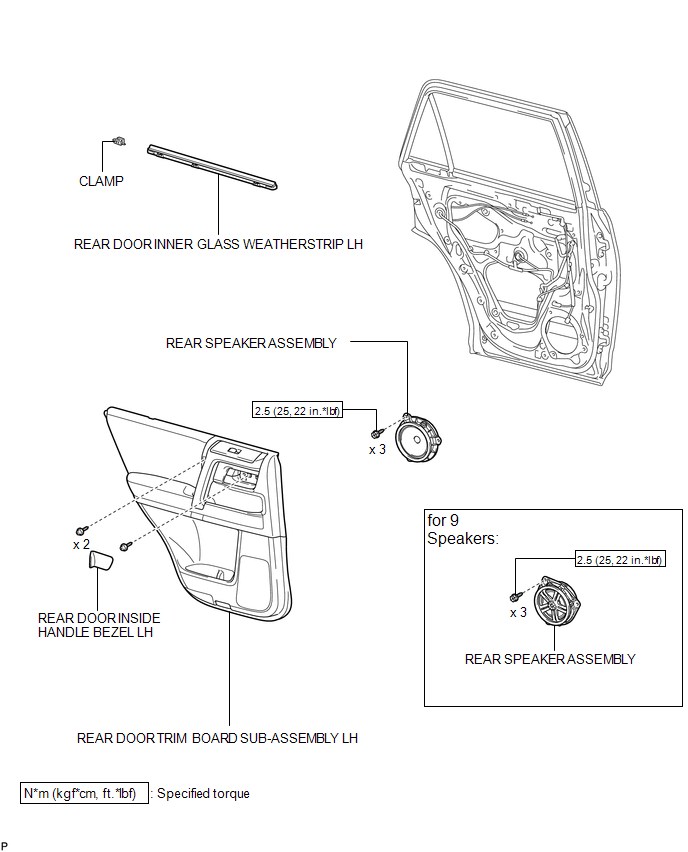
COMPONENTS
ILLUSTRATION
Removal
REMOVAL
CAUTION / NOTICE / HINT
HINT:
- Use the same procedure for the RH and LH sides.
- The procedure listed below is for the LH side.
PROCEDURE
1. REMOVE REAR DOOR INSIDE HANDLE BEZEL LH
.gif)
2. REMOVE REAR DOOR TRIM BOARD SUB-ASSEMBLY LH
3. REMOVE REAR DOOR INNER GLASS WEATHERSTRIP LH
4. REMOVE REAR SPEAKER ASSEMBLY
|
(a) Disconnect the speaker connector. |
|
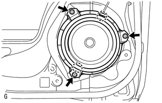
(b) Remove the 3 screws.
(c) Detach the 2 claws and remove the speaker.
NOTICE:
Do not touch the cone of the speaker.
Inspection
INSPECTION
PROCEDURE
1. INSPECT REAR SPEAKER ASSEMBLY (for 8 Speakers)
|
(a) Measure the resistance according to the value(s) in the table below. Standard Resistance:
If the result is not as specified, replace the rear speaker assembly. Text in Illustration
|
|
.png)
2. INSPECT REAR SPEAKER ASSEMBLY (for 9 Speakers)
(a) Temporarily replace the rear speaker assembly with a new or normally functioning one.
OK:
Malfunction disappears.
Installation
INSTALLATION
CAUTION / NOTICE / HINT
HINT:
- Use the same procedure for the RH and LH sides.
- The procedure listed below is for the LH side.
PROCEDURE
1. INSTALL REAR SPEAKER ASSEMBLY
(a) Temporarily install the speaker by attaching the 2 claws of the speaker to the door panel.
(b) Install the speaker with the 3 screws.
Torque:
2.5 N·m {25 kgf·cm, 22 in·lbf}
NOTICE:
Do not touch the cone of the speaker.
(c) Connect the connector.
2. INSTALL REAR DOOR INNER GLASS WEATHERSTRIP LH
.gif)
3. INSTALL REAR DOOR TRIM BOARD SUB-ASSEMBLY LH
4. INSTALL REAR DOOR INSIDE HANDLE BEZEL LH
 Radio Receiver
Components
COMPONENTS
ILLUSTRATION
ILLUSTRATION
Removal
REMOVAL
PROCEDURE
1. REMOVE NO. 1 INSTRUMENT CLUSTER FINISH PANEL GARNISH
2. REMOVE NO. 2 INSTRUMENT CLUSTER FINISH PANEL GAR ...
 Satellite Radio Antenna
Components
COMPONENTS
ILLUSTRATION
Removal
REMOVAL
PROCEDURE
1. DISCONNECT CABLE FROM NEGATIVE BATTERY TERMINAL
CAUTION:
Wait at least 90 seconds after disconnecting the cable from the n ...
Other materials about Toyota 4Runner:
Problem Symptoms Table
PROBLEM SYMPTOMS TABLE
HINT:
Use the table below to help determine the cause of problem symptoms. If multiple
suspected areas are listed, the potential causes of the symptoms are listed in order
of probability in the "Suspected Area" column of ...
Removal
REMOVAL
CAUTION / NOTICE / HINT
HINT:
Use the same procedure for the RH and LH sides.
The procedure listed below is for the LH side.
PROCEDURE
1. DISCONNECT CABLE FROM NEGATIVE BATTERY TERMINAL
CAUTION:
Wait at least 90 seconds after d ...

0.0173