Toyota 4Runner: Rear Brake Flexible Hose
Components
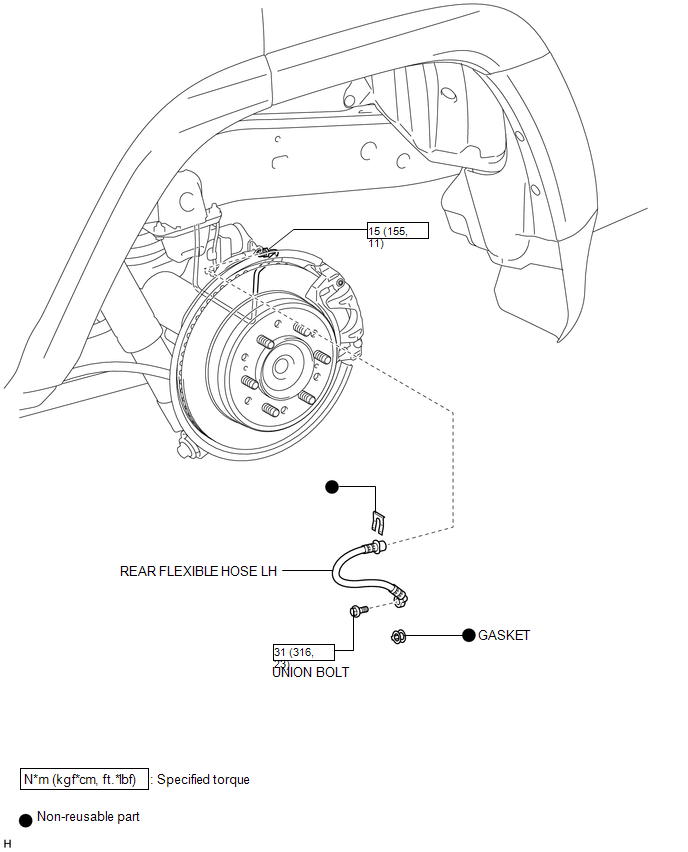
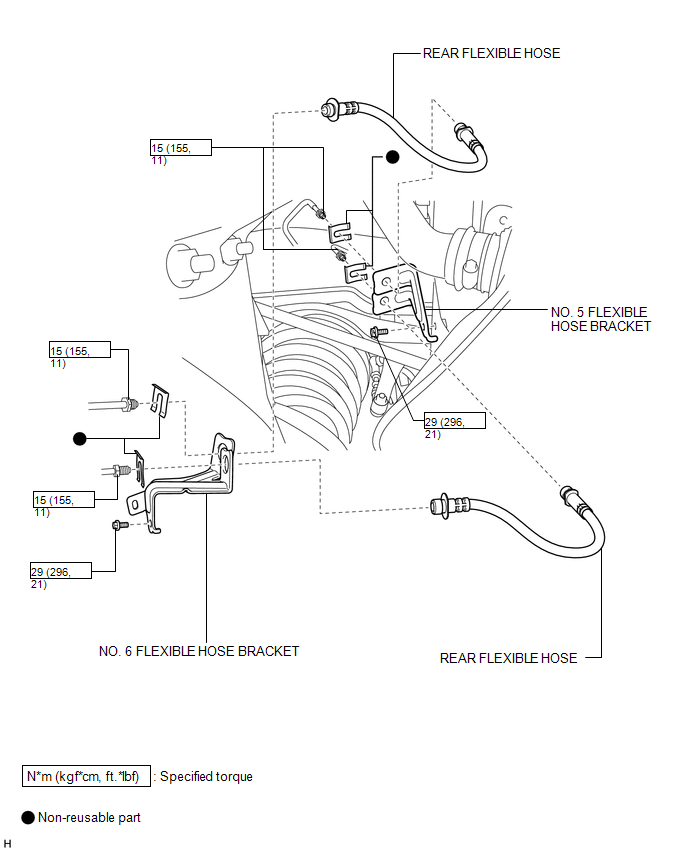
COMPONENTS
ILLUSTRATION
ILLUSTRATION
Removal
REMOVAL
CAUTION / NOTICE / HINT
HINT:
- Use the same procedure for the RH and LH sides.
- The procedure listed below is for the LH side.
PROCEDURE
1. REMOVE REAR WHEEL
2. DRAIN BRAKE FLUID
NOTICE:
Wash off brake fluid immediately if it comes in contact with any painted surface.
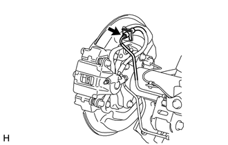
3. REMOVE REAR FLEXIBLE HOSE LH
|
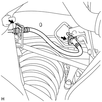
(a) Remove the union bolt, gasket and rear flexible hose from the rear disc brake cylinder. |
|
.png)
|
(b) Disconnect the brake tube from the rear flexible hose with a union nut wrench while holding the rear flexible hose with a wrench. NOTICE:
|
|
(c) Remove the clip.
4. REMOVE REAR FLEXIBLE HOSE
|
(a) Disconnect each brake tube from the rear flexible hose with a union nut wrench while holding the rear flexible hose with a wrench. |
|
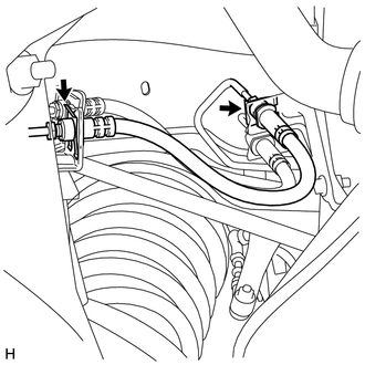
(b) Remove the 2 clips.
(c) Remove the rear flexible hose.
|
(d) Disconnect each brake tube from the rear flexible hose with a union nut wrench while holding the rear flexible hose with a wrench. |
|
(e) Remove the 2 clips.
(f) Remove the rear flexible hose.
5. REMOVE NO. 5 FLEXIBLE HOSE BRACKET
|
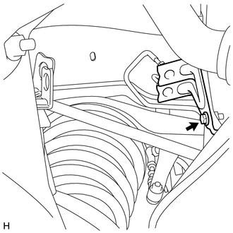
(a) Remove the bolt and bracket from the upper arm bracket. |
|
6. REMOVE NO. 6 FLEXIBLE HOSE BRACKET
(a) Remove the bolt and bracket from the rear axle housing.
Installation
INSTALLATION
CAUTION / NOTICE / HINT
HINT:
- Use the same procedure for the RH and LH sides.
- The procedure listed below is for the LH side.
PROCEDURE
1. INSTALL NO. 5 FLEXIBLE HOSE BRACKET
(a) Install the bracket with the bolt.
Torque:
29 N·m {296 kgf·cm, 21 ft·lbf}
NOTICE:
Make sure the bracket rotation stopper touches the installation position.
2. INSTALL NO. 6 FLEXIBLE HOSE BRACKET
(a) Install the bracket with the bolt.
Torque:
29 N·m {296 kgf·cm, 21 ft·lbf}
3. INSTALL REAR FLEXIBLE HOSE
(a) Connect the rear flexible hose to the connecting point with each brake tube, and then install 2 new clips.
(b) Using a union nut wrench, connect each brake tube to the rear flexible hose while holding the rear flexible hose with a wrench.
Torque:
15 N·m {155 kgf·cm, 11 ft·lbf}
NOTICE:
- Do not bend or damage the brake tube.
- Do not allow any foreign matter such as dirt and dust to enter the brake tube from the connecting point.
- Use the formula to calculate special torque values for situations where
a union nut wrench is combined with a torque wrench (See page
.gif) ).
).
(c) Connect the rear flexible hose to the connecting point with each brake tube, and then install 2 new clips.
(d) Using a union nut wrench, connect each brake tube to the rear flexible hose while holding the rear flexible hose with a wrench.
Torque:
15 N·m {155 kgf·cm, 11 ft·lbf}
NOTICE:
- Do not bend or damage the brake tube.
- Do not allow any foreign matter such as dirt and dust to enter the brake tube from the connecting point.
- Use the formula to calculate special torque values for situations where
a union nut wrench is combined with a torque wrench (See page
).
4. INSTALL REAR FLEXIBLE HOSE LH
(a) Connect the rear flexible hose to the connecting point with the brake tube, and then install a new clip.
(b) Using a union nut wrench, connect the brake tube to the rear flexible hose while holding the rear flexible hose with a wrench.
Torque:
15 N·m {155 kgf·cm, 11 ft·lbf}
NOTICE:
- Do not bend or damage the brake tube.
- Do not allow any foreign matter such as dirt and dust to enter the brake tube from the connecting point.
- Use the formula to calculate special torque values for situations where
a union nut wrench is combined with a torque wrench (See page
).
(c) Install the rear flexible hose and a new gasket to the rear disc brake cylinder with the union bolt.
Torque:
31 N·m {316 kgf·cm, 23 ft·lbf}
HINT:
Install the rear flexible hose lock securely to the lock hole in the cylinder.
5. BLEED BRAKE LINE
6. INSTALL REAR WHEEL
 Installation
INSTALLATION
CAUTION / NOTICE / HINT
HINT:
Use the same procedure for the RH and LH sides.
The procedure listed below is for the LH side.
PROCEDURE
1. INSTALL REAR DISC
(a) Ali ...

Other materials about Toyota 4Runner:
Center Airbag Sensor Assembly
Components
COMPONENTS
ILLUSTRATION
On-vehicle Inspection
ON-VEHICLE INSPECTION
PROCEDURE
1. CHECK AIRBAG SENSOR ASSEMBLY (VEHICLE NOT INVOLVED IN COLLISION)
(a) Perform a diagnostic system check (See page
).
2. CHECK AIRBAG SENSOR ASSEMBLY (VEH ...
Turbine Speed Sensor Circuit No Signal (P0717)
DESCRIPTION
This sensor detects the rotation speed of the turbine which indicates the input
speed of the transmission. By comparing the input turbine speed signal NT with the
counter gear speed sensor signal SP2, the ECM detects the shift timing of the ge ...

0.0132