Toyota 4Runner: Installation
INSTALLATION
CAUTION / NOTICE / HINT
CAUTION:
Wear protective gloves. Sharp areas on the parts may injure your hands.
HINT:
- Use the same procedure for the RH and LH sides.
- The procedure listed below is for the LH side.
PROCEDURE
1. INSTALL FRONT SEAT ASSEMBLY
(a) Place the front seat assembly in the cabin.
NOTICE:
Be careful not to damage the vehicle body.
(b) Connect the seat wire connectors under the seat.
(c) Temporarily install the front seat assembly with the 4 bolts.
(d) Connect the cable to the negative (-) battery terminal.
NOTICE:
When disconnecting the cable, some systems need to be initialized after the cable
is reconnected (See page .gif) ).
).
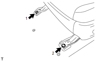
(e) Operate the power seat switch to move the front seat assembly to the rearmost position.
|
(f) Tighten the 2 bolts in the order indicated in the illustration. Torque: 37 N·m {377 kgf·cm, 27 ft·lbf} |
|
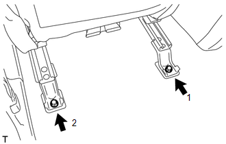
(g) Operate the power seat switch to move the front seat assembly to the foremost position.
|
(h) Tighten the 2 bolts in the order indicated in the illustration. Torque: 37 N·m {377 kgf·cm, 27 ft·lbf} |
|
2. INSTALL OUTER SEAT TRACK COVER LH

(a) Move the outer seat track cover LH in the direction of the arrow to attach the 4 guides.
(b) Attach the 2 claws to install the outer seat track cover LH.
3. INSTALL INNER SEAT TRACK BRACKET COVER LH
(a) Move the inner seat track bracket cover LH in the direction of the arrow to attach the 2 guides.
(b) Attach the 2 claws to install the inner seat track bracket cover LH.
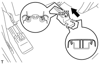
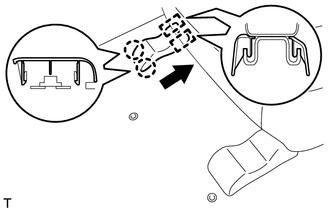
4. INSTALL FRONT SEAT OUTER TRACK BRACKET COVER LH
(a) Operate the power seat switch to move the front seat assembly to the rearmost position.
|
(b) Move the front seat outer track bracket cover LH in the direction of the arrow to attach the 2 claws and guide. |
|
(c) Attach the 2 claws to install the front seat outer track bracket cover LH.
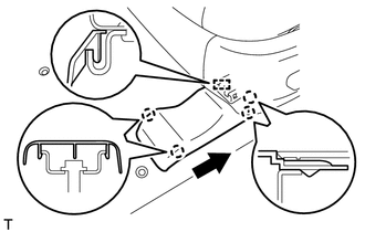
5. INSTALL FRONT SEAT INNER TRACK BRACKET COVER LH
(a) Move the front seat inner track bracket cover LH in the direction of the arrow to attach the 2 guides.
(b) Attach the 2 claws to install the front seat inner track bracket cover LH.
6. INSTALL FRONT SEAT HEADREST ASSEMBLY
(a) Install the front seat headrest assembly.
7. CHECK SRS WARNING LIGHT
(See page )
8. INSPECT POWER SEAT CONTROL SYSTEM (w/o Memory)
(See page )
9. INSPECT POWER SEAT CONTROL SYSTEM (w/ Memory)
(See page )
10. INSPECT SEAT HEATER SYSTEM (w/ Seat Heater System)
(See page )
11. INSPECT CLIMATE CONTROL SEAT SYSTEM (w/ Climate Control Seat System)
(See page )
 Removal
REMOVAL
CAUTION / NOTICE / HINT
CAUTION:
Wear protective gloves. Sharp areas on the parts may injure your hands.
HINT:
Use the same procedure for the RH and LH sides.
The procedure li ...

Other materials about Toyota 4Runner:
Symbols used in illustrations
Safety symbol
The symbol of a circle with a slash through it means “Do not”, “Do not do
this”, or “Do not let this happen”.
Arrows indicating operations
Indicates the action (pushing,
turning, etc.) used to operate switches and other de ...
Problem Symptoms Table
PROBLEM SYMPTOMS TABLE
HINT:
Use the table below to help determine the cause of problem symptoms. If multiple
suspected areas are listed, the potential causes of the symptoms are listed in order
of probability in the "Suspected Area" column of ...

0.0064