Toyota 4Runner: Rear Coil Spring
Components
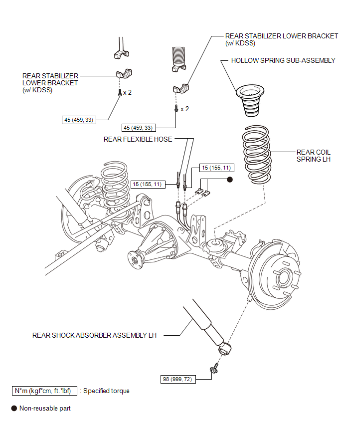
COMPONENTS
ILLUSTRATION
Removal
REMOVAL
CAUTION / NOTICE / HINT
HINT:
- Use the same procedure for the RH and LH sides.
- The procedure listed below is for the LH side.
PROCEDURE
1. REMOVE REAR WHEEL
2. REMOVE REAR STABILIZER LOWER BRACKET (w/ KDSS)
.gif)
3. DISCONNECT REAR SHOCK ABSORBER ASSEMBLY LH
(a) Support the rear axle housing.
|
(b) Remove the bolt on the lower side of the shock absorber. |
|
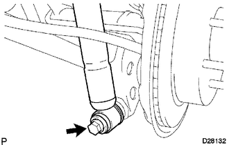
(c) Disconnect the shock absorber from the axle housing.
4. DISCONNECT REAR FLEXIBLE HOSE
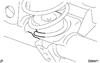
5. REMOVE REAR COIL SPRING LH
(a) While lowering the axle housing, remove the coil spring.
NOTICE:
Be careful not to snap the brake line and parking brake cable.
6. REMOVE HOLLOW SPRING SUB-ASSEMBLY
(a) Remove the hollow spring from the frame.
Installation
INSTALLATION
CAUTION / NOTICE / HINT
HINT:
- Use the same procedure for the RH and LH sides.
- The procedure listed below is for the LH side.
- A bolt without a torque specification is shown in the standard bolt
chart (See page
.gif) ).
).
PROCEDURE
1. INSTALL HOLLOW SPRING SUB-ASSEMBLY
(a) Install the hollow spring to the frame.
2. INSTALL REAR COIL SPRING LH
|
(a) Install the rear coil spring to the rear axle housing. HINT: Before installing the coil spring, check that the coil spring end is in the correct position. If not, reinstall the coil spring. |
|
3. TEMPORARILY INSTALL REAR SHOCK ABSORBER ASSEMBLY LH
(a) Temporarily install the lower side of the shock absorber with the bolt.
4. INSTALL REAR STABILIZER LOWER BRACKET (w/ KDSS)
5. STABILIZE SUSPENSION
6. TIGHTEN REAR SHOCK ABSORBER ASSEMBLY LH
(a) Tighten the bolt.
Torque:
98 N·m {999 kgf·cm, 72 ft·lbf}
7. CONNECT REAR FLEXIBLE HOSE
8. FILL RESERVOIR WITH BRAKE FLUID
9. BLEED BRAKE LINE
10. CHECK FLUID LEVEL IN RESERVOIR
11. CHECK FOR BRAKE FLUID LEAK
12. INSTALL REAR WHEEL
Torque:
for aluminum wheel :
103 N·m {1050 kgf·cm, 76 ft·lbf}
for steel wheel :
112 N·m {1142 kgf·cm, 83 ft·lbf}
 Rear Suspension
...
 Rear Lateral Control Rod
Components
COMPONENTS
ILLUSTRATION
Removal
REMOVAL
PROCEDURE
1. REMOVE REAR LATERAL CONTROL ROD ASSEMBLY
(a) Remove the bolt.
...
Other materials about Toyota 4Runner:
Sound Quality is Bad Only when CD is Played (Volume is Too Low)
PROCEDURE
1.
REPLACE CD AND RECHECK
(a) Replace the CD with a known good one and check that the malfunction disappears.
OK:
Malfunction disappears.
OK
END
NG
REPLACE RADIO AN ...
Mechanical System Tests
MECHANICAL SYSTEM TESTS
1. STALL SPEED TEST
HINT:
This test is to check the overall performance of the engine and transmission.
CAUTION:
To ensure safety, perform this test in an open and level area that provides
good traction.
The stall s ...

0.0264