Toyota 4Runner: Rear Lateral Control Rod
Components
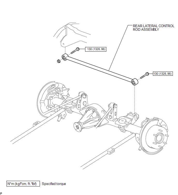
COMPONENTS
ILLUSTRATION
Removal
REMOVAL
PROCEDURE
1. REMOVE REAR LATERAL CONTROL ROD ASSEMBLY
|
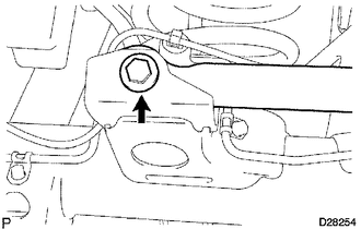
(a) Remove the bolt. |
|
|
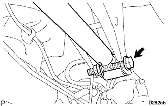
(b) Remove the bolt, nut and lateral control rod assembly. HINT: Turn the bolt while holding the nut. |
|
Installation
INSTALLATION
PROCEDURE
1. TEMPORARILY INSTALL REAR LATERAL CONTROL ROD ASSEMBLY
(a) Temporarily install the lateral control rod assembly with the bolt and nut.
(b) Temporarily tighten the bolt.
2. STABILIZE SUSPENSION
.gif)
3. TIGHTEN REAR LATERAL CONTROL ROD ASSEMBLY
|
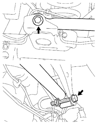
(a) Tighten the 2 bolts. Torque: 130 N·m {1326 kgf·cm, 96 ft·lbf} HINT: Turn the bolt while holding the nut. |
|
 Rear Coil Spring
Components
COMPONENTS
ILLUSTRATION
Removal
REMOVAL
CAUTION / NOTICE / HINT
HINT:
Use the same procedure for the RH and LH sides.
The procedure listed below is for the LH side. ...
 Rear Lower Arm
Components
COMPONENTS
ILLUSTRATION
Removal
REMOVAL
CAUTION / NOTICE / HINT
HINT:
Use the same procedure for the RH and LH sides.
The procedure listed below is for the LH side. ...
Other materials about Toyota 4Runner:
Scanning radio stations (excluding XM® Satellite Radio)
Scanning the preset radio stations
Press and hold
until you hear a beep.
Preset stations will be played for 5 seconds each.
When the desired station is
reached, press again.
Scanning all radio stations within range
Press
.
All the stations wit ...
Installation
INSTALLATION
PROCEDURE
1. INSTALL TRANSFER ASSEMBLY
(a) Install the transfer to the transmission.
(b) Install the 8 bolts.
Torque:
24 N·m {245 kgf·cm, 18 ft·lbf}
2. INSTALL AUTOMATIC TRANSMISSION ASSEMBLY
(a) Install the automatic transmission (See ...

0.0258