Toyota 4Runner: Rear No. 2 Seat Inner Belt Assembly
Components
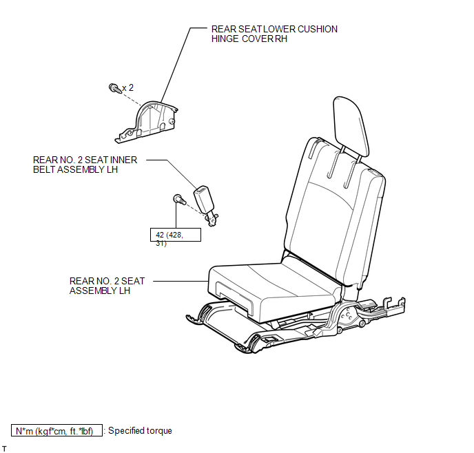
COMPONENTS
ILLUSTRATION
Installation
INSTALLATION
CAUTION / NOTICE / HINT
HINT:
A bolt without a torque specification is shown in the standard bolt chart (See
page .gif) ).
).
PROCEDURE
1. INSTALL REAR NO. 2 SEAT INNER BELT SUB-ASSEMBLY
(a) Using a T45 "TORX" socket wrench, install the inner belt assembly with the bolt.
Torque:
42 N·m {428 kgf·cm, 31 ft·lbf}
2. INSTALL REAR SEAT LOWER CUSHION HINGE COVER RH
3. INSTALL REAR NO. 2 SEAT ASSEMBLY LH
(a) Install the rear No. 2 seat assembly LH (See page
).
Removal
REMOVAL
CAUTION / NOTICE / HINT
CAUTION:
Wear protective gloves. Sharp areas on the parts may injure your hands.
HINT:
- Use the same procedure for the RH and LH sides.
- The procedure listed below is for the LH side.
PROCEDURE
1. REMOVE REAR NO. 2 SEAT ASSEMBLY LH
(a) Remove the rear No. 2 seat assembly LH (See page
.gif) ).
).
2. REMOVE REAR SEAT LOWER CUSHION HINGE COVER RH
3. REMOVE REAR NO. 2 SEAT INNER BELT ASSEMBLY LH
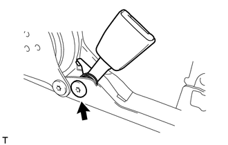
(a) Using a T45 "TORX" socket wrench, remove the bolt and inner belt assembly.
 Installation
INSTALLATION
CAUTION / NOTICE / HINT
HINT:
Use the same procedure for the RH and LH sides.
The procedure listed below is for the LH side.
A bolt without a torque specification is sh ...

Other materials about Toyota 4Runner:
Rocker Panel Moulding(w/ Intuitive Parking Assist System)
Components
COMPONENTS
ILLUSTRATION
Installation
INSTALLATION
CAUTION / NOTICE / HINT
HINT:
Use the same procedure for both the RH and LH sides.
The procedure listed below is for the LH side.
PROCEDURE
1. INSTALL NO. 6 ROCKER PA ...
IG2 Signal Malfunction (B2788)
DESCRIPTION
The steering lock ECU determines the on/off status of the engine switch through
the IG2 signal circuit.
The steering lock ECU does not lock the steering when it receives the IG2 relay
on signal. This prevents the steering from being locked wh ...

0.0265