Toyota 4Runner: Installation
INSTALLATION
CAUTION / NOTICE / HINT
HINT:
- Use the same procedure for the RH and LH sides.
- The procedure listed below is for the LH side.
- A bolt without a torque specification is shown in the standard bolt
chart (See page
.gif) ).
).
PROCEDURE
1. INSTALL REAR NO. 1 SEAT OUTER BELT ASSEMBLY LH
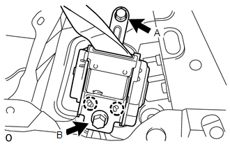
(a) Align the claws with the seat belt positioning holes and install the retractor of the seat belt with the bolt as shown in the illustration.
HINT:
First install bolt A, and then install bolt B.
Torque:
for bolt A :
7.5 N·m {76 kgf·cm, 66 in·lbf}
for bolt B :
42 N·m {428 kgf·cm, 31 ft·lbf}
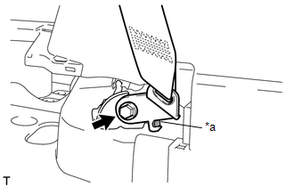
(b) Install the rear No. 1 seat outer belt shoulder anchor with the bolt.
Torque:
42 N·m {428 kgf·cm, 31 ft·lbf}
2. INSTALL REAR NO. 2 SEATBACK LOCK STRIKER SUB-ASSEMBLY LH (w/ Rear No. 2 Seat)
(a) Install the seatback lock striker (See page
).
3. INSTALL REAR WINDOW SIDE GARNISH ASSEMBLY LH
4. INSTALL REAR NO. 2 WINDOW SIDE GARNISH ASSEMBLY LH
5. INSTALL DECK TRIM SIDE PANEL ASSEMBLY LH
(a) w/o Rear No. 2 Seat:
(1) Pass the rear seatback lock control lever base through the deck trim side panel.
(2) Attach the 4 claws and 2 guides to install the rear seatback lock control lever base to the deck trim side panel.
(3) Attach the 7 clips, 5 claws and 2 guides to install the deck trim side panel.
(4) Install the 3 bolts and 2 screws.
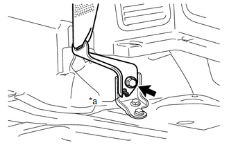
(5) Install the rear No. 1 seat outer belt floor anchor with the bolt.
Torque:
42 N·m {428 kgf·cm, 31 ft·lbf}
(b) w/ Rear No. 2 Seat:
(1) Attach the 7 clips, 5 claws and 2 guides to install the deck trim side panel.
(2) Install the 3 bolts and 2 screws.
(3) Install the rear No. 1 seat outer belt floor anchor with the bolt.
Torque:
42 N·m {428 kgf·cm, 31 ft·lbf}
|
(4) for LH Side: Install the rear No. 2 seat outer belt floor anchor with the bolt. Torque: 42 N·m {428 kgf·cm, 31 ft·lbf} NOTICE: Do not allow the anchor part of the anchor plate sub-assembly to overlap the protruding parts of the vehicle body. Text in Illustration
|
|
|
(5) for RH Side: Install the rear No. 2 seat outer belt floor anchor with the bolt. Torque: 42 N·m {428 kgf·cm, 31 ft·lbf} NOTICE: Do not allow the anchor part of the anchor plate sub-assembly to overlap the protruding parts of the vehicle body. Text in Illustration
|
|
6. INSTALL NO. 1 LUGGAGE COMPARTMENT TRIM COVER
7. INSTALL FRONT DECK SIDE TRIM COVER LH
8. INSTALL NO. 1 LUGGAGE COMPARTMENT TRIM HOOK
9. INSTALL REAR NO. 1 SEAT OUTER LAP BELT ANCHOR COVER
10. INSTALL REAR FLOOR CARPET ASSEMBLY (w/o Deck Board)
11. INSTALL REAR FLOOR MAT REAR SUPPORT PLATE
12. INSTALL INNER FLOOR SIDE RAIL SUB-ASSEMBLY (w/ Deck Board)
13. INSTALL DECK BOARD ASSEMBLY (w/ Deck Board)
14. INSTALL LUGGAGE COMPARTMENT SIDE COVER SUB-ASSEMBLY LH (w/ Deck Board)
15. INSTALL LUGGAGE COMPARTMENT SIDE COVER SUB-ASSEMBLY RH (w/ Deck Board)
16. INSTALL REAR NO. 2 FLOOR BOARD ASSEMBLY (w/ Deck Board)
17. INSTALL NO. 2 DECK BOARD SUB-ASSEMBLY (w/ Deck Board)
18. INSTALL NO. 2 LUGGAGE COMPARTMENT TRIM COVER (w/ Deck Board, w/o Rear No. 2 Seat)
19. INSTALL NO. 1 DECK BOARD SUB-ASSEMBLY (w/o Deck Board)
20. INSTALL NO. 1 LUGGAGE COMPARTMENT TRIM COVER (w/o Deck Board)
21. INSTALL REAR DOOR OPENING TRIM WEATHERSTRIP LH
22. INSTALL REAR DOOR SCUFF PLATE LH
23. INSTALL QUARTER SCUFF PLATE LH (w/ Rear No. 2 Seat)
 Removal
REMOVAL
CAUTION / NOTICE / HINT
HINT:
Use the same procedure for the RH and LH sides.
The procedure listed below is for the LH side.
PROCEDURE
1. REMOVE REAR NO. 1 FLOOR STEP CO ...
 Rear No. 2 Seat Inner Belt Assembly
Components
COMPONENTS
ILLUSTRATION
Installation
INSTALLATION
CAUTION / NOTICE / HINT
HINT:
A bolt without a torque specification is shown in the standard bolt chart (See
page ).
PROCE ...
Other materials about Toyota 4Runner:
Seat Memory Switch
Components
COMPONENTS
ILLUSTRATION
Removal
REMOVAL
PROCEDURE
1. REMOVE FRONT DOOR LOWER FRAME BRACKET GARNISH LH
2. REMOVE NO. 2 DOOR INSIDE HANDLE BEZEL LH
3. REMOVE FRONT DOOR TRIM BOARD SUB-ASSEMBLY LH
4. REMOVE FRONT DOOR INNER GLAS ...
Disposal
DISPOSAL
CAUTION / NOTICE / HINT
CAUTION:
Before performing pre-disposal deployment of any SRS part, review and closely
follow all applicable environmental and hazardous material regulations. Pre-disposal
deployment may be considered hazardous material ...

0.0123