Toyota 4Runner: Rear Power Window Switch
Components
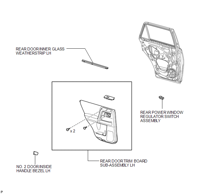
COMPONENTS
ILLUSTRATION
Inspection
INSPECTION
PROCEDURE
1. INSPECT REAR POWER WINDOW REGULATOR SWITCH ASSEMBLY
|
(a) Measure the resistance according to the value(s) in the table below. Standard Resistance:
|
|
.png)
(b) Check that the LED illuminates.
(1) Apply battery voltage to the power window regulator switch and check that the LED illuminates.
OK:
|
Measurement Condition |
Specified Condition |
|---|---|
|
Battery positive (+) → 4 (LED) Battery negative (-) → 1 (GND) |
LED illuminates |
- If the result is not as specified, replace the rear power window regulator switch assembly.
|
*1 |
LED |
|
*a |
Front view of wire harness connector (Power Window Regulator Switch Assembly) |
Removal
REMOVAL
PROCEDURE
1. REMOVE NO. 2 DOOR INSIDE HANDLE BEZEL LH
.gif)
2. REMOVE REAR DOOR TRIM BOARD SUB-ASSEMBLY LH
3. REMOVE REAR DOOR INNER GLASS WEATHERSTRIP LH
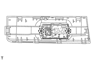
4. REMOVE REAR POWER WINDOW REGULATOR SWITCH ASSEMBLY
(a) Detach the 10 claws from the backside and remove the power window regulator switch with base panel.
.png)
(b) Disconnect the connector.
|
(c) Detach the 2 claws and remove the power window regulator switch. |
|
Installation
INSTALLATION
PROCEDURE
1. INSTALL REAR POWER WINDOW REGULATOR SWITCH ASSEMBLY
(a) Attach the 2 claws to install the power window regulator switch assembly to the base panel.
(b) Connect the connector.
(c) Attach the 10 claws to the install the power window regulator switch with base panel.
2. INSTALL REAR DOOR INNER GLASS WEATHERSTRIP LH
.gif)
3. INSTALL REAR DOOR TRIM BOARD SUB-ASSEMBLY LH
4. INSTALL NO. 2 DOOR INSIDE HANDLE BEZEL LH
 Installation
INSTALLATION
CAUTION / NOTICE / HINT
HINT:
Use the same procedure for both the RH and LH sides.
The procedure listed below is for the LH side.
PROCEDURE
1. INSTALL QUARTER WINDO ...
 Relay(for Window Defogger)
On-vehicle Inspection
ON-VEHICLE INSPECTION
PROCEDURE
1. REMOVE DEFOGGER RELAY (DEF)
(a) Remove the defogger relay from the engine room relay block.
Text in Illustration
...
Other materials about Toyota 4Runner:
Inspection
INSPECTION
PROCEDURE
1. INSPECT REAR WIPER MOTOR AND BRACKET ASSEMBLY
(a) Check the wiper intermittent operation.
(1) Connect the positive (+) lead of the battery to terminal 5 (L) and
the negative (-) lead to terminal 4 (E), and check tha ...
Removal
REMOVAL
PROCEDURE
1. TABLE OF BOLT, SCREW AND NUT
HINT:
All bolts, screws and nuts relevant to installing and removing the instrument
panel are shown along with their alphabet code in the table below.
2. DISCONNECT CABLE FROM NEGATIVE BATTERY TERMINAL ...

0.0085