Toyota 4Runner: Reassembly
REASSEMBLY
CAUTION / NOTICE / HINT
HINT:
- Use the same procedure for the RH and LH sides.
- The procedure listed below is for the LH side.
PROCEDURE
1. INSTALL FRONT TURN SIGNAL LIGHT BULB
(a) Install the front turn signal light bulb to the front turn signal light socket.
2. INSTALL FRONT TURN SIGNAL LIGHT SOCKET
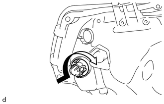
|
(a) Turn the front turn signal light socket in the direction indicated by the arrow to install it. |
|
3. INSTALL FRONT SIDE MARKER LIGHT BULB
(a) Install the front side marker light bulb to the front side marker light socket.
4. INSTALL FRONT SIDE MARKER LIGHT SOCKET
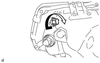
|
(a) Turn the front side marker light socket in the direction indicated by the arrow to install it. |
|
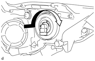
5. INSTALL NO. 2 HEADLIGHT BULB
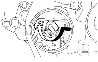
|
(a) Turn the No. 2 headlight bulb in the direction indicated by the arrow to install it. |
|
(b) Connect the connector.
6. INSTALL HEADLIGHT SOCKET COVER
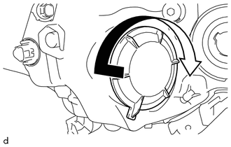
|
(a) Turn the headlight socket cover in the direction indicated by the arrow to install it. |
|
7. INSTALL NO. 1 HEADLIGHT BULB
|
(a) Turn the No. 1 headlight bulb in the direction indicated by the arrow to install it. |
|
 Adjustment
ADJUSTMENT
CAUTION / NOTICE / HINT
HINT:
Use the same procedure for the RH and LH sides.
The procedure listed below is for the LH side.
PROCEDURE
1. VEHICLE PREPARATION FOR HEAD ...
 Installation
INSTALLATION
CAUTION / NOTICE / HINT
HINT:
Use the same procedure for both the RH and LH sides.
The procedure listed below is for the LH side.
PROCEDURE
1. INSTALL FRONT BUMPER ...
Other materials about Toyota 4Runner:
Portable Player cannot be Registered
CAUTION / NOTICE / HINT
HINT:
Some versions of "Bluetooth" compatible audio players may not function, or the
function may be limited using the navigation receiver assembly, even if the portable
audio player itself can play files (See page ).
...
Precaution
PRECAUTION
1. IGNITION SWITCH EXPRESSIONS
(a) The type of ignition switch used on this model differs depending on the specifications
of the vehicle. The expressions listed in the table below are used in this section.
Expression
Ignit ...
0.0065

