Toyota 4Runner: Reassembly
REASSEMBLY
PROCEDURE
1. INSTALL SLIDING ROOF DRIVE CABLE SUB-ASSEMBLY
|
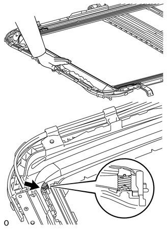
(a) Hold down the window deflector. NOTICE: Make sure that the spring indicated by the arrow in the illustration is securely installed. |
|
(b) Using a screwdriver, slide the drive cable in the direction indicated by the arrow in the illustration to install it.
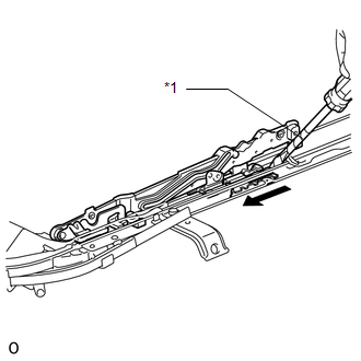
HINT:
Tape the screwdriver tip before use.
Text in Illustration|
*1 |
Protective Tape |
.png) |
Slide |
|
(c) Slide the rear roof drip channel forward and attach the 2 claws to install it. Text in Illustration
|
|
(d) Install the 2 stoppers with the 2 screws.
.png)
2. ADJUST SLIDING ROOF DRIVE CABLE SUB-ASSEMBLY
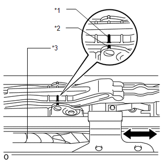
(a) Using a screwdriver, align the matchmarks by sliding the drive cable in the directions indicated by the arrow in the illustration.
HINT:
Tape the screwdriver tip before use.
Text in Illustration|
*1 |
Matchmark A |
|
*2 |
Matchmark B |
|
*3 |
Protective Tape |
3. INSTALL SLIDING ROOF SUNSHADE STOPPER LH
|
(a) Install the stopper. |
|
.png)
4. INSTALL SLIDING ROOF SUNSHADE STOPPER RH
HINT:
Use the same procedures described for the LH side.
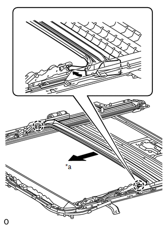
5. INSTALL SUNSHADE TRIM SUB-ASSEMBLY
(a) Insert the sunshade trim into the sliding roof housing.
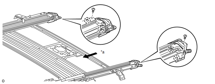 Text in Illustration
|
*a |
Forward |
- |
- |
(b) Attach the 4 claws to install the sliding roof piece LH and RH.
(c) Install the 2 screws.
6. INSTALL SLIDING ROOF DRIVE GEAR SUB-ASSEMBLY
(a) Install the drive gear with the 2 bolts.
Torque:
5.5 N·m {56 kgf·cm, 49 in·lbf}
|
(b) Attach the bracket claw to install the bracket. |
|
.png)
 Installation
INSTALLATION
PROCEDURE
1. INSTALL SLIDING ROOF HOUSING SUB-ASSEMBLY
(a) Temporarily install the housing with the 8 bolts (vehicle body side) and
8 nuts.
(b) Tighten the 8 nuts in alphabetical or ...

Other materials about Toyota 4Runner:
On-vehicle Inspection
ON-VEHICLE INSPECTION
PROCEDURE
1. CHECK TURN SIGNAL FLASHER ASSEMBLY
(a) Measure the resistance according to the value(s) in the table below.
Standard Resistance:
Tester Connection
Condition
...
Unable To Connect To Call Center
DESCRIPTION
This may occur when the intensity of the telephone radio frequency was very weak,
PRL updates are required or the Safety Connect system has a malfunction, and a DTC
is stored.
PROCEDURE
1.
CHECK COMMUNICATION SERVICE C ...

0.0066