Toyota 4Runner: Installation
INSTALLATION
PROCEDURE
1. INSTALL SLIDING ROOF HOUSING SUB-ASSEMBLY
(a) Temporarily install the housing with the 8 bolts (vehicle body side) and 8 nuts.
(b) Tighten the 8 nuts in alphabetical order.
Torque:
5.5 N·m {56 kgf·cm, 49 in·lbf}
(c) Tighten the 8 bolts in alphabetical order.
Torque:
8.0 N·m {82 kgf·cm, 71 in·lbf}
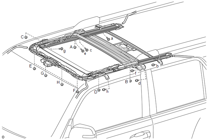
(d) Connect the 4 sliding roof drain hoses.
2. INSTALL SLIDING ROOF WEATHERSTRIP
(a) Install the sliding roof weatherstrip as described below.
(1) Attach each corner of the weatherstrip so that each weatherstrip mark is aligned with the sliding roof glass center mark. After attaching the entire weatherstrip, check that all weatherstrip marks are within the sliding roof glass end marks.
(2) Make sure the weatherstrip cutout is toward the rear side of the vehicle and centered.
(3) Make sure the weatherstrip is securely installed as shown in the illustration.
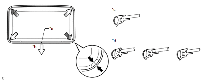 Text in Illustration
|
*a |
Cutout |
*b |
Rear Side |
|
*c |
CORRECT |
*d |
INCORRECT |
3. INSTALL SLIDING ROOF GLASS SUB-ASSEMBLY
|
(a) Using a T25 "TORX" driver, temporarily install the glass with the 4 screws. |
|
.png)
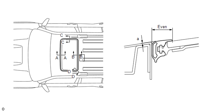
(b) Perform a level check.
(1) Check the difference in the level between the roof panel and upper surface of the weatherstrip labeled "a" when the sliding roof glass is fully closed.
Standard:
|
Area |
Specified Condition |
|---|---|
|
A - A |
0 +/-1.5 mm (0 +/-0.0591 in.) |
|
B - B |
|
|
C - C |
|
|
D - D |
HINT:
"+" represents the condition that the glass is above the panel level. "-" represents the condition that the glass is below the panel level.
(2) Perform a gap check.
Check the gap between the roof panel and roof glass.
NOTICE:
The gap must be even all around.
|
(c) Tighten the 4 screws. Torque: 5.5 N·m {56 kgf·cm, 49 in·lbf} |
|
4. CHECK FOR WATER LEAK
(a) After adjusting the sliding roof glass sub-assembly, check for water leakage into the vehicle interior.
If there are any leaks, readjust the sliding roof glass sub-assembly.
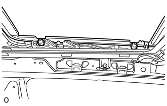
5. INSTALL SLIDING ROOF SIDE GARNISH LH
.png)
(a) Attach the 5 claws to install the sliding roof side garnish.
6. INSTALL SLIDING ROOF SIDE GARNISH RH
HINT:
Use the same procedures described for the LH side.
7. INSTALL CURTAIN SHIELD AIRBAG ASSEMBLY LH
(a) Install the curtain shield airbag assembly LH (See page
.gif) ).
).
8. INSTALL CURTAIN SHIELD AIRBAG ASSEMBLY RH
HINT:
Use the same procedures described for the LH side.
9. INSTALL ROOF HEADLINING ASSEMBLY
(a) Install the roof headlining assembly (See page
).
10. CONNECT CABLE TO NEGATIVE BATTERY TERMINAL
NOTICE:
When disconnecting the cable, some systems need to be initialized after the cable
is reconnected (See page ).
11. CHECK SRS WARNING LIGHT
(a) Check the SRS warning light (See page ).
 Disassembly
DISASSEMBLY
PROCEDURE
1. REMOVE SLIDING ROOF DRIVE GEAR SUB-ASSEMBLY
(a) Detach the bracket claw and remove the bracket.
(b) Remove the 2 bolts ...
 Reassembly
REASSEMBLY
PROCEDURE
1. INSTALL SLIDING ROOF DRIVE CABLE SUB-ASSEMBLY
(a) Hold down the window deflector.
NOTICE:
Make sure that the spring indicated by the arrow in the illustrati ...
Other materials about Toyota 4Runner:
Brake
General Maintenance
GENERAL MAINTENANCE
PROCEDURE
1. INSPECT BRAKE LINE PIPES AND HOSES
HINT:
Work in a well-lighted area. Turn the front wheels fully to the right or left
before beginning the inspection.
(a) Using a mirror, check the enti ...
Precaution
PRECAUTION
1. TIRE PRESSURE WARNING ECU EXPRESSIONS
(a) The tire pressure monitor receiver assembly is referred to as the tire pressure
warning ECU in this section.
2. TIRE PRESSURE WARNING SYSTEM PRECAUTION
(a) It is necessary for the tire pressures to ...

0.0083