Toyota 4Runner: Reassembly
REASSEMBLY
CAUTION / NOTICE / HINT
HINT:
- Use the same procedure for the RH and LH sides.
- The procedure listed below is for the LH side.
PROCEDURE
1. TEMPORARILY INSTALL FRONT DISC BRAKE BLEEDER PLUG
(a) Temporarily install the front disc brake bleeder plug to the disc brake cylinder assembly.
HINT:
The front disc brake bleeder plug will be tightened to the torque specification in the "Bleed Brake Line" procedure.
(b) Install the front disc brake bleeder plug cap to the bleeder plug.
2. INSTALL PISTON SEAL
|
(a) Apply a light coat of lithium soap base glycol grease to the entire inner and outer circumference of 4 new piston seals. Text in Illustration
|
|
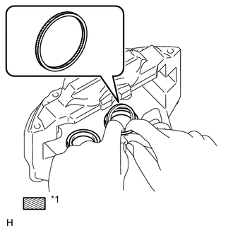
(b) Install the 4 piston seals to the disc brake cylinder assembly.
3. INSTALL FRONT DISC BRAKE PISTON
|
(a) Apply a light coat of lithium soap base glycol grease to the entire inner circumference of 4 new cylinder boots. Text in Illustration
|
|
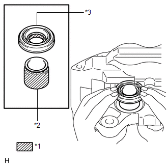
(b) Apply a light coat of lithium soap base glycol grease to the entire outer circumference of the 4 front disc brake pistons where they contact the cylinder boots and front disc brake cylinder.
(c) Install the 4 cylinder boots to the 4 front disc brake pistons.
(d) Install the 4 front disc brake pistons to the front disc brake cylinder.
NOTICE:
Do not forcibly install the piston into the disc brake cylinder.
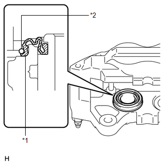
4. INSTALL CYLINDER BOOT
|
(a) Install one side of each of the 4 cylinder boots to the front disc brake cylinder. Text in Illustration
NOTICE:
|
|
5. INSTALL FRONT DISC BRAKE SET RING
(a) Install the 4 front disc brake set rings.
 Inspection
INSPECTION
PROCEDURE
1. CHECK BRAKE CYLINDER AND PISTON
(a) Check the cylinder bore and piston for rust or scoring.
If necessary, replace the disc brake cylinder assembly.
2. CHECK PAD LINING THI ...
 Installation
INSTALLATION
CAUTION / NOTICE / HINT
HINT:
Use the same procedure for the RH and LH sides.
The procedure listed below is for the LH side.
PROCEDURE
1. INSTALL FRONT DISC
(a) Al ...
Other materials about Toyota 4Runner:
Id Code Box
Components
COMPONENTS
ILLUSTRATION
Installation
INSTALLATION
PROCEDURE
1. INSTALL ID CODE BOX
(a) Attach the 2 claws and move the ID code box in the direction of the
arrow.
(b) M ...
Automatic transmission
Select a shift position appropriate for the driving conditions.
Shifting the shift lever
Vehicles without a smart key
system:
While the engine switch is in the “ON” position, move the shift lever with
the brake pedal depressed.
Vehicles with a s ...

0.1169