
Toyota 4Runner: Inspection
INSPECTION
PROCEDURE
1. CHECK BRAKE CYLINDER AND PISTON
(a) Check the cylinder bore and piston for rust or scoring.
If necessary, replace the disc brake cylinder assembly.
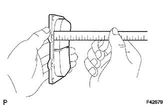
2. CHECK PAD LINING THICKNESS
|
(a) Using a ruler, measure the pad lining thickness. Standard thickness: 11.3 mm (0.445 in.) Minimum thickness: 1.0 mm (0.0394 in.) If the pad lining thickness is less than the minimum, replace the pad. |
|
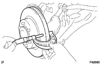
3. CHECK DISC THICKNESS
|
(a) Using a micrometer, measure the disc thickness. Standard thickness: 32.0 mm (1.26 in.) Minimum thickness: 29.0 mm (1.14 in.) If the disc thickness is less than the minimum, replace the disc. |
|
4. CHECK DISC RUNOUT
|
(a) Install the disc with the 6 hub nuts. Torque: for aluminum wheel : 103 N·m {1050 kgf·cm, 76 ft·lbf} for steel wheel : 112 N·m {1142 kgf·cm, 83 ft·lbf} |
|
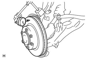
(b) Using a dial indicator, measure the disc runout 10 mm (0.394 in.) from the outer edge of the disc.
Maximum disc runout:
0.05 mm (0.00197 in.)
If the disc runout is more than the maximum, check the bearing play in the axial
direction and the axle hub runout (See page .gif) ).
).
If the bearing play and axle hub runout are normal, adjust the disc runout or grind
the disc using an "On-car" brake lathe.
(c) Remove the 6 hub nuts and disc.
 Disassembly
DISASSEMBLY
CAUTION / NOTICE / HINT
HINT:
Use the same procedure for the RH and LH sides.
The procedure listed below is for the LH side.
PROCEDURE
1. REMOVE FRONT DISC BRAKE SET ...
 Reassembly
REASSEMBLY
CAUTION / NOTICE / HINT
HINT:
Use the same procedure for the RH and LH sides.
The procedure listed below is for the LH side.
PROCEDURE
1. TEMPORARILY INSTALL FRONT DI ...
Other materials about Toyota 4Runner:
On-vehicle Inspection
ON-VEHICLE INSPECTION
PROCEDURE
1. INSPECT DRIVE BELT
(a) Visually check the belt for excessive wear, frayed cords, etc.
If any defect is found, replace the drive belt.
HINT:
Cracks on the rib side of a belt are considered acceptable. Replace the belt
...
Removal
REMOVAL
PROCEDURE
1. DISCONNECT CABLE FROM NEGATIVE BATTERY TERMINAL
CAUTION:
Wait at least 90 seconds after disconnecting the cable from the negative (-)
battery terminal to disable the SRS system.
NOTICE:
When disconnecting the cable, some systems ne ...

0.0114