Toyota 4Runner: Reassembly
REASSEMBLY
CAUTION / NOTICE / HINT
NOTICE:
Do not allow foreign matter, etc. to contact the rear axle hub and bearing assembly.
PROCEDURE
1. INSTALL BRAKE DRUM OIL DEFLECTOR LH
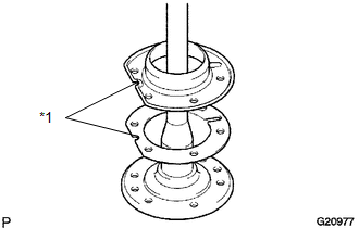
(a) Install a new deflector gasket and deflector to the rear axle shaft.
HINT:
Align the 2 oil drain holes.
Text in Illustration|
*1 |
Oil Drain Holes |
(b) Insert 6 new hub bolts.
|
(c) Temporarily install a washer and nut to each hub bolt as shown in the illustration. |
|
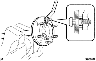
(d) Install the hub bolts by tightening each nut.
(e) Remove the washer and nut from each hub bolt.
2. INSTALL REAR AXLE HUB AND BEARING ASSEMBLY LH
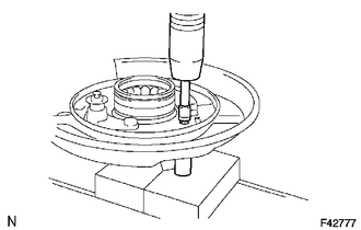
(a) Install a new rear axle hub and bearing to the parking brake plate.
NOTICE:
Make sure the bearing is securely installed to the parking brake plate.
|
(b) Using 2 socket wrenches and a press, press in the 4 housing bolts. |
|
3. INSTALL REAR AXLE SHAFT LH
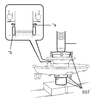
(a) Install a new washer and a new retainer to the axle hub as shown in the illustration.
Text in Illustration|
*a |
Tapered Surface |
|
*b |
Chamfered Surface |
NOTICE:
- Install the washer with its tapered surface facing downward.
- Install the retainer with its chamfered surface facing downward.
(b) Using SST and a press, press in the rear axle shaft.
SST: 09631-12090
SST: 09726-40010
SST: 09951-01100
NOTICE:
Make sure the bearing is securely installed to the rear axle shaft.
4. INSTALL REAR AXLE SHAFT SNAP RING LH
.png)
(a) Using snap ring expander, install a new rear axle shaft snap ring.
 Inspection
INSPECTION
PROCEDURE
1. INSPECT REAR AXLE SHAFT
(a) Using a dial indicator, measure the rear axle shaft runout and flange runout.
Maximum runout:
Shaft runout: 1.50 mm (0.0591 in.)
Flange run ...
 Installation
INSTALLATION
CAUTION / NOTICE / HINT
HINT:
Use the same procedure for the RH and LH sides.
The procedure listed below is for the LH side.
PROCEDURE
1. INSTALL REAR AXLE SHAFT OI ...
Other materials about Toyota 4Runner:
Reassembly
REASSEMBLY
CAUTION / NOTICE / HINT
NOTICE:
Do not allow foreign matter, etc. to contact the rear axle hub and bearing assembly.
PROCEDURE
1. INSTALL BRAKE DRUM OIL DEFLECTOR LH
(a) Install a new deflector gasket and deflector to the rear axle shaft.
H ...
TC and CG Terminal Circuit
DESCRIPTION
DTC output mode is set by connecting terminals 13 (TC) and 4 (CG) of the DLC3.
The DTCs are output by the blinking of the tire pressure warning light.
WIRING DIAGRAM
HINT:
When each warning light blinks continuously, a ground short in the w ...

0.027