Toyota 4Runner: Reassembly
REASSEMBLY
PROCEDURE
1. INSTALL REAR PROPELLER SHAFT UNIVERSAL JOINT SPIDER BEARING
HINT:
Use the same procedure for all rear propeller shaft universal joint spider bearing.
|
(a) Apply MP grease to the universal joint spider and new bearings. NOTICE: Be careful not to apply too much grease. |
|
.png)
(b) Install the universal joint spider to the propeller shaft.
|
(c) Using SST, install 2 of the bearings to the universal joint spider. SST: 09332-25010 |
|
.png)
(d) Using SST, adjust both bearings so that the snap ring grooves are at maximum and equal width.
SST: 09332-25010
(e) Install 4 new snap rings of equal thickness which will allow no axial play.
.png)
HINT:
Do not reuse the snap rings.
Thickness of snap ring (Both ends thin type):
|
Parts No. |
Specified Condition |
Mark |
|---|---|---|
|
90520-25039 |
2.28 to 2.30 mm (0.0898 to 0.0906 in.) |
1 |
|
90520-25040 |
2.30 to 2.32 mm (0.0906 to 0.0913 in.) |
2 |
|
90520-25041 |
2.32 to 2.34 mm (0.0913 to 0.0921 in.) |
- |
|
90520-25042 |
2.34 to 2.36 mm (0.0921 to 0.0929 in.) |
Brown |
|
90520-25043 |
2.36 to 2.38 mm (0.0929 to 0.0937 in.) |
Blue |
|
90520-25044 |
2.38 to 2.40 mm (0.0937 to 0.0945 in.) |
6 |
|
90520-25045 |
2.40 to 2.42 mm (0.0945 to 0.0953 in.) |
7 |
|
90520-25046 |
2.42 to 2.44 mm (0.0953 to 0.0961 in.) |
8 |
|
90520-25047 |
2.44 to 2.46 mm (0.0961 to 0.0969 in.) |
.png) |
|
90520-25048 |
2.46 to 2.48 mm (0.0969 to 0.0976 in.) |
10 |
|
90520-25049 |
2.48 to 2.50 mm (0.0976 to 0.0984 in.) |
A |
|
90520-25050 |
2.50 to 2.52 mm (0.0984 to 0.0992 in.) |
B |
|
90520-25051 |
2.52 to 2.54 mm (0.0992 to 0.1000 in.) |
C |
|
90520-25052 |
2.54 to 2.56 mm (0.1000 to 0.1008 in.) |
D |
|
90520-25053 |
2.56 to 2.58 mm (0.1008 to 0.1016 in.) |
E |
|
90520-25054 |
2.18 to 2.20 mm (0.0858 to 0.0866 in.) |
J |
|
90520-25055 |
2.20 to 2.22 mm (0.0866 to 0.0874 in.) |
K |
|
90520-25056 |
2.22 to 2.24 mm (0.0874 to 0.0882 in.) |
F |
|
90520-25057 |
2.24 to 2.26 mm (0.0882 to 0.0890 in.) |
G |
|
90520-25058 |
2.26 to 2.28 mm (0.0890 to 0.0898 in.) |
H |
NOTICE:
- Must use a new retainer ring.
- Must use retainer rings of the same thickness as possible on both ends.
(f) Using a hammer, tap the yoke until there is no clearance between the spider bearing outer race and snap ring.
HINT:
Install a new spider bearing on the sleeve side in the procedure described above.
2. INSPECT PROPELLER SHAFT ASSEMBLY
HINT:
When replacing the spider bearing, be sure that the grease fitting assembly hole is facing to the direction shown in the illustration.
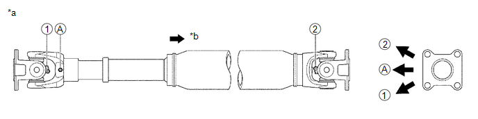 Text in Illustration
|
*a |
Spider grease fitting assembly direction for propeller shaft assembly |
*b |
Rear Side |
3. INSPECT REAR PROPELLER SHAFT UNIVERSAL JOINT SPIDER BEARING
.gif)
 Installation
INSTALLATION
PROCEDURE
1. INSTALL PROPELLER SHAFT ASSEMBLY
(a) Align the matchmarks on the propeller shaft flange and differential flange.
(b) Install the propeller shaft assembly with the 4 washe ...
 Propeller Shaft System
Problem Symptoms Table
PROBLEM SYMPTOMS TABLE
HINT:
Use the table below to help determine the cause of the problem symptom. The potential
causes of the symptoms are listed in order of probabili ...
Other materials about Toyota 4Runner:
Disassembly
DISASSEMBLY
CAUTION / NOTICE / HINT
HINT:
Use the same procedure for the RH and LH sides.
The procedure listed below is for the LH side.
PROCEDURE
1. REMOVE FRONT DISC BRAKE SET RING
(a) Using a screwdriver, remove the 4 fron ...
Lost Communication with ECM (U0100,U0142,U0155)
DESCRIPTION
The air conditioning amplifier communicates with the ECM, main body ECU (multiplex
network body ECU) and combination meter through the CAN communication system.
DTC Code
DTC Detection Condition
Trouble Area
...

0.0118