Toyota 4Runner: Removal
REMOVAL
CAUTION / NOTICE / HINT
HINT:
- Use the same procedure for the RH and LH sides.
- The procedure listed below is for the LH side.
PROCEDURE
1. REMOVE FRONT WHEEL
2. REMOVE LOWER FRONT BUMPER COVER (w/ KDSS)
.gif)
3. REMOVE NO. 1 ENGINE UNDER COVER SUB-ASSEMBLY (w/ KDSS)
4. REMOVE FRONT SUSPENSION MEMBER BRACE SUB-ASSEMBLY (w/ KDSS)
5. REMOVE FRONT STABILIZER END BRACKET (w/ KDSS)
6. REMOVE FRONT STABILIZER BAR (w/ KDSS)
7. DISCONNECT FRONT SHOCK ABSORBER WITH COIL SPRING
|
(a) Remove the bolt, nut and washer. |
|
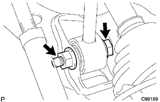
(b) Disconnect the front shock absorber with coil spring from the suspension lower arm.
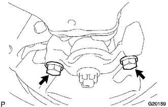
8. REMOVE FRONT NO. 1 SUSPENSION LOWER ARM SUB-ASSEMBLY LH
|
(a) Remove the 2 bolts and disconnect the front lower ball joint attachment LH from the steering knuckle. |
|
|
(b) Place matchmarks on the No. 2 camber adjust cam and toe adjust cam sub-assembly. Text in Illustration
|
|
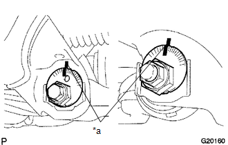
(c) Remove the nut, No. 2 camber adjust cam, camber adjust cam assembly, bolt, toe adjust cam sub-assembly, No. 2 toe adjust plate and front No. 1 suspension lower arm sub-assembly LH.
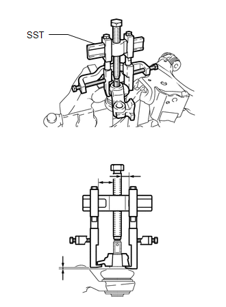
(d) Remove the cotter pin and nut.
|
(e) Using SST, remove the front lower ball joint attachment LH. SST: 09950-40011 09951-04010 09954-04010 09955-04031 09955-04061 09958-04011 09952-04010 |
|
 On-vehicle Inspection
ON-VEHICLE INSPECTION
PROCEDURE
1. REMOVE FRONT WHEEL
2. INSPECT FRONT SUSPENSION LOWER NO. 1 ARM
(a) Install the hub nuts to the disc.
(b) Using a dial indicator, check the lower ball ...
 Disassembly
DISASSEMBLY
PROCEDURE
1. REMOVE FRONT NO. 1 LOWER ARM BUSH LH
(a) Using a chisel and hammer, pry the flange of the bush outward.
(b) ...
Other materials about Toyota 4Runner:
XM Tuner Antenna Disconnected (B15FE,B15FF)
DESCRIPTION
These DTCs are stored when a malfunction occurs in the satellite radio antenna
assembly which is connected to the stereo component tuner assembly.
DTC No.
DTC Detection Condition
Trouble Area
B1 ...
Steering Angle Sensor Communication Stop Mode
DESCRIPTION
Detection Item
Symptom
Trouble Area
Steering Angle Sensor Communication Stop Mode
Either condition is met:
"Spiral cable (Steering Angle Sensor)" is not displayed ...

0.0228