Toyota 4Runner: Removal
REMOVAL
CAUTION / NOTICE / HINT
NOTICE:
Be sure to read PRECAUTION before performing this procedure (See page
.gif) ).
).
PROCEDURE
1. REMOVE FRONT WHEEL
2. REMOVE REAR WHEEL
3. REMOVE CENTER CONTROL ABSORBER ASSEMBLY LH
|
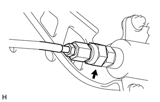
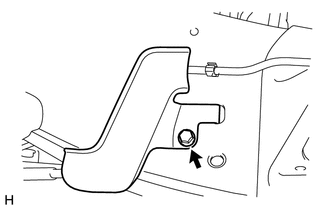
(a) While using a wrench to hold the bracket, disconnect the joint. NOTICE: Check that all four shock absorbers are fully extended to the normal suspension rebound point. |
|
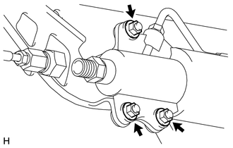
(b) Remove the bolt and disconnect the bracket.
|
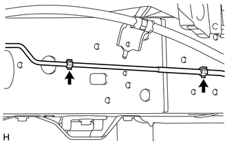
(c) Disconnect the tube from the 2 clamps. |
|
|
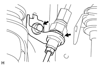
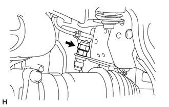
(d) While using a wrench to hold the center control absorber assembly, disconnect the joint. NOTICE:
|
|
|
(e) Remove the 3 nuts and center control absorber assembly. NOTICE:
|
|
4. REMOVE CENTER CONTROL ABSORBER ASSEMBLY RH
HINT:
Use the same procedure described for the LH side.
5. REMOVE TUBE PROTECTOR LH
|
(a) Remove the bolt and tube protector LH. |
|
6. REMOVE TUBE PROTECTOR RH
HINT:
Use the same procedure described for the LH side.
7. REMOVE NO. 1 CENTER CONTROL ABSORBER TUBE LH
|
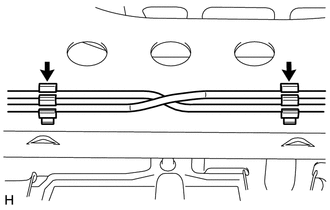
(a) While using a wrench to hold the bracket, disconnect the joint. |
|
|
(b) Using pliers, cut the center control absorber tube. Use a container to catch suspension fluid as it drains out. Text in Illustration
|
|
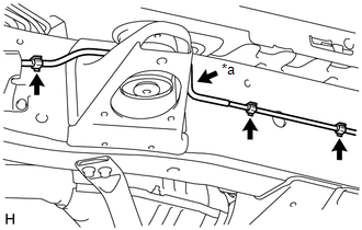
(c) Detach the 3 clamps from the frame.
|
(d) Detach the 2 clamps. |
|
(e) Remove the No. 1 center control absorber tube LH.
8. REMOVE NO. 1 CENTER CONTROL ABSORBER TUBE RH
HINT:
Use the same procedure described for the LH side.
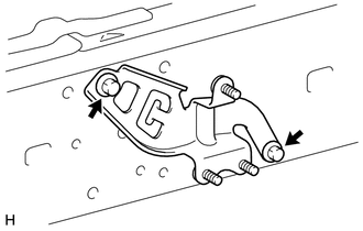
9. REMOVE CENTER CONTROL ABSORBER BRACKET LH
|
(a) Remove the 2 bolts and center control absorber bracket LH from the frame. |
|
10. REMOVE CENTER CONTROL ABSORBER BRACKET RH
HINT:
Use the same procedure described for the LH side.
 Components
COMPONENTS
ILLUSTRATION
ILLUSTRATION
ILLUSTRATION
...
 Installation
INSTALLATION
PROCEDURE
1. INSTALL CENTER CONTROL ABSORBER BRACKET LH
(a) Install the center control absorber bracket with the 2 bolts.
Torque:
29 N·m {296 kgf·cm, 21 ft·lbf}
2. INSTALL CENTE ...
Other materials about Toyota 4Runner:
Precaution
PRECAUTION
1. IGNITION SWITCH EXPRESSION
HINT:
The type of ignition switch used on this model differs depending on the specifications
of the vehicle. The expressions listed in the table below are used in this section.
Expression
Ign ...
Disassembly
DISASSEMBLY
PROCEDURE
1. REMOVE GENERATOR PULLEY CAP
(a) Using a screwdriver, remove the generator pulley cap.
2. REMOVE GENERATOR WITH CLUTCH PULLEY
(a) Mount the generator in a vise between aluminum p ...

0.007