Toyota 4Runner: Removal
REMOVAL
PROCEDURE
1. REMOVE FRONT WHEEL
2. REMOVE REAR WHEEL
3. REMOVE INSTALL GROUND SPARE TIRE
4. REMOVE TIRE PRESSURE WARNING VALVE AND TRANSMITTER
(a) Remove the valve cap and valve core to release the air from the tire.
NOTICE:
Keep the removed valve cap.
(b) After ensuring that a sufficient amount of air has been released, using an 11 mm deep socket wrench, remove the nut and washer used to secure the tire pressure warning valve and transmitter.
Then drop the tire pressure warning valve and transmitter with the grommet into the tire.
HINT:
The grommet may remain attached to the rim.
|
(c) After dropping the tire pressure warning valve and transmitter into the tire, disengage the bead using the shoe of a tire remover. Text in Illustration
NOTICE:
|
|
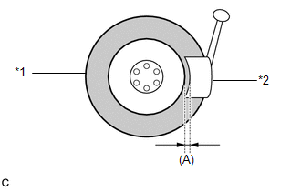
(d) Separate the upper bead.
(e) Take out the tire pressure warning valve and transmitter with the grommet from the tire and separate the lower bead.
(f) Remove the grommet from the tire pressure warning valve and transmitter.
 Components
COMPONENTS
ILLUSTRATION
...
 Installation
INSTALLATION
CAUTION / NOTICE / HINT
NOTICE:
Always use a new grommet and valve core when installing the tire pressure
warning valve and transmitter.
Check that the washer and nut a ...
Other materials about Toyota 4Runner:
General Information
GENERAL INFORMATION
A large number of ECU controlled systems are used in the 4RUNNER. In
general, ECU controlled systems are considered to be very intricate, requiring
a high level of technical knowledge to troubleshoot. However, most problem
...
On-vehicle Inspection
ON-VEHICLE INSPECTION
PROCEDURE
1. INSPECT BRAKE FLUID LEVEL IN RESERVOIR
(a) Check the fluid level and add fluid if necessary.
Brake Fluid:
SAE J1703 or FMVSS No. 116 DOT3
HINT:
Add fluid to the reservoir MAX line.
...

0.0274