Toyota 4Runner: Removal
REMOVAL
PROCEDURE
1. REMOVE FRONT BUMPER COVER (w/o Intuitive Parking Assist System)
(See Page .gif) )
)
2. REMOVE FRONT BUMPER COVER (w/ Intuitive Parking Assist System)
(See Page )
3. REMOVE HIGH PITCHED HORN ASSEMBLY
4. REMOVE RADIATOR GRILLE BRACKET
5. REMOVE LOW PITCHED HORN ASSEMBLY
6. REMOVE HOOD LOCK CONTROL CABLE COVER
|
(a) Remove the 2 bolts. |
|
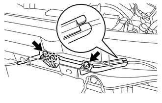
(b) Detach the claw to remove the hood lock control cable cover.
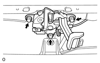
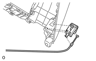
7. REMOVE HOOD LOCK ASSEMBLY
|
(a) Remove the 3 bolts. |
|
|
(b) Detach the clamp. |
|
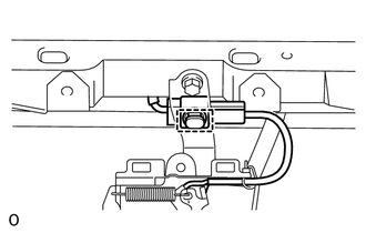
(c) w/ Engine Hood Courtesy Switch:
Disconnect the connector.
(d) w/o Engine Hood Courtesy Switch:
Disconnect the connector cap.
(e) Disconnect the hood lock control cable and remove the hood lock assembly.
8. REMOVE DOOR SCUFF PLATE ASSEMBLY LH
9. REMOVE COWL SIDE TRIM BOARD LH
10. REMOVE HOOD LOCK CONTROL LEVER SUB-ASSEMBLY
|
(a) Detach the clamp. |
|
|
(b) Detach the 3 claws. |
|
(c) Disconnect the hood lock control cable assembly and remove the hood lock control lever sub-assembly.
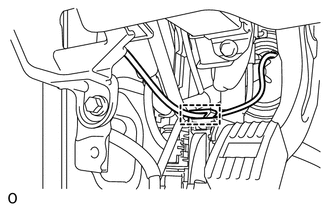
11. REMOVE HOOD LOCK CONTROL CABLE ASSEMBLY
(a) Using a screwdriver, disconnect the 3 clamps as shown in the illustration.
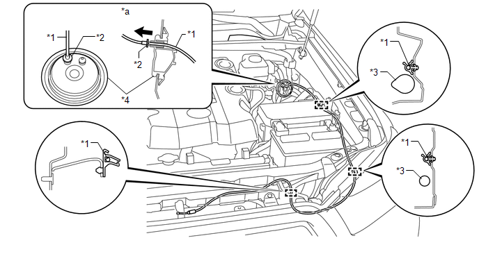 Text in Illustration
|
*1 |
Hood Lock Control Cable Assembly |
*2 |
Stopper |
|
*3 |
Wire Harness |
*4 |
Grommet |
|
*a |
Engine Room Side |
- |
- |
HINT:
Tape the screwdriver tip before use.
(b) Pull the hood lock control cable assembly from the engine compartment to remove it.
 Components
COMPONENTS
ILLUSTRATION
...
 Installation
INSTALLATION
PROCEDURE
1. INSTALL HOOD LOCK CONTROL CABLE ASSEMBLY
(a) Tie the string that was passed through the engine compartment to
the end of the hood lock control cable assembl ...
Other materials about Toyota 4Runner:
Maintenance data (fuel, oil level, etc.)
Dimensions and weights
Vehicle identification
Vehicle identification number
The vehicle identification number (VIN) is the legal identifier for your
vehicle. This is the primary identification number for your Toyota. It is used
in registering the own ...
Diagnostic Trouble Code Chart
DIAGNOSTIC TROUBLE CODE CHART
If a trouble code is output during the DTC check, inspect the trouble
areas listed for that code. For details of the code, refer to the "See page"
below.
When the SRS warning light remains on and the ...

0.0262