Toyota 4Runner: Removal
REMOVAL
PROCEDURE
1. REMOVE ASSIST STRAP HOLE COVER
.gif)
2. REMOVE ASSIST STRAP ASSEMBLY
3. REMOVE BACK DOOR TRIM PANEL ASSEMBLY
4. REMOVE MULTIPLEX NETWORK DOOR ECU
5. REMOVE NO. 2 BACK DOOR SERVICE HOLE COVER
6. REMOVE BACK DOOR LOCK CYLINDER (w/o Smart Key System)
7. REMOVE BACK DOOR OUTSIDE GARNISH (w/o Smart Key System)
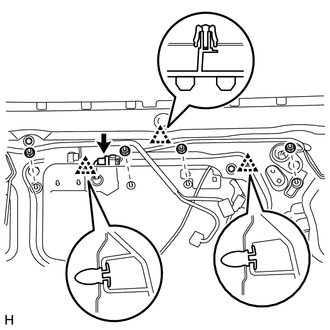
(a) Disconnect the connector.
(b) Remove the 4 nuts.
(c) Detach the 3 clips and remove the back door outside garnish.
8. REMOVE BACK DOOR OUTSIDE GARNISH (w/ Smart Key System)
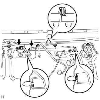
(a) Disconnect the 2 connectors.
(b) Remove the 4 nuts.
(c) Detach the 3 clips and back door outside garnish.
 Components
COMPONENTS
ILLUSTRATION
ILLUSTRATION
...
 Disassembly
DISASSEMBLY
PROCEDURE
1. REMOVE BACK DOOR OPENER SWITCH ASSEMBLY
2. REMOVE NO. 2 BACK DOOR OUTSIDE GARNISH
(a) Detach the 2 clips and No. 2 back door outside garnish.
3. REMOVE LICENSE PLATE ...
Other materials about Toyota 4Runner:
Telematics Transceiver Malfunction (B15A8)
DESCRIPTION
This DTC is stored when an error in EEPROM or PLL IC is detected during the DCM
(Telematics Transceiver) self-check. The EEPROM (Electrically Erasable Programmable
Read-Only Memory) stores the various data to operate Safety Connect. The PLL IC ...
If the engine will not start
If the engine will not start even though correct starting procedures are
being followed (, 173), consider each of the following points:
The engine will not start even though the starter motor operates normally.
One of the following may be the cause of the ...

0.0256