Toyota 4Runner: Terminals Of Ecu
TERMINALS OF ECU
1. TERMINALS OF ECU
 Text in Illustration
|
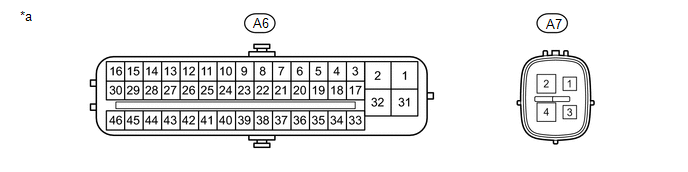
*a |
Component without harness connected (Skid Control ECU) |
- |
- |
|
Terminal No. (Symbol) |
Terminal Description |
|---|---|
|
A6-1 (GND1) |
Skid control ECU ground |
|
A6-2 (+BM1) |
Power supply for motor |
|
A6-3 (FR+) |
Front speed sensor RH power supply output |
|
A6-4 (FL-) |
Front speed sensor LH input |
|
A6-5 (RR+) |
Rear speed sensor RH power supply output |
|
A6-6 (RL-) |
Rear speed sensor LH input |
|
A6-7 (STP) |
Stop light switch assembly |
|
A6-9 (CSW) |
VSC OFF switch |
|
A6-11 (CANH) |
CAN communication terminal H |
|
A6-12 (SP1) |
Speedometer signal |
|
A6-13 (ATRC)*2 |
A-TRAC switch |
|
A6-16 (STPO) |
Stop light switch assembly |
|
A6-17 (FR-) |
Front speed sensor RH input |
|
A6-18 (FL+) |
Front speed sensor LH power supply output |
|
A6-19 (RR-) |
Rear speed sensor RH input |
|
A6-20 (RL+) |
Rear speed sensor LH power supply output |
|
A6-24 (TS) |
Sensor test terminal (Signal check switch) |
|
A6-25 (CANL) |
CAN communication terminal L |
|
A6-27 (EXI)*2 |
for Part-time 4WD: A.D.D. detection switch for Full-time 4WD: Center differential lock detection switch |
|
A6-31 (+BS) |
Power supply for solenoid |
|
A6-32 (GND2) |
Skid control ECU ground |
|
A6-40 (EXI3) |
w/ Rear Differential Lock: Rear differential lock detection switch w/o Rear Differential Lock*1: IG power supply w/o Rear Differential Lock*2: Front wheel drive ECU |
|
A6-41 (LBL) |
Brake fluid level warning switch |
|
A6-44 (HDCS)*3 |
Downhill assist control switch |
|
A6-45 (STP2) |
Stop light switch assembly |
|
A6-46 (IG1) |
IG1 power supply |
|
A7-1 (IG2) |
IG2 power supply |
|
A7-2 (+BM2) |
Power supply for motor |
|
A7-4 (GND3) |
Skid control ECU ground |
- *1: for 2WD
- *2: for 4WD
- *3: w/ Downhill Assist Control
2. TERMINAL INSPECTION
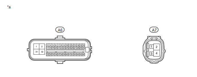
(a) Disconnect the connector and measure the voltage or resistance on the wire harness side.
HINT:
The voltage cannot be measured with the connector connected to the skid control ECU as the connector is watertight.
 Text in Illustration
|
*a |
Front view of wire harness connector (to Skid Control ECU) |
- |
- |
|
Terminal No. (Symbol) |
Wiring Color |
Terminal Description |
Condition |
Specified Condition |
|---|---|---|---|---|
|
A6-1 (GND1) - Body ground |
W-B |
Ground |
Always |
Below 1 Ω |
|
A6-2 (+BM1) - Body ground |
B |
Power supply for motor (from battery) |
Always |
11 to 14 V |
|
A6-7 (STP) - Body ground |
L |
Stop light switch assembly |
Brake pedal depressed → released |
8 to 14 V → Below 1.5 V |
|
A6-9 (CSW) - Body ground |
V-W |
VSC OFF switch input |
VSC OFF switch off → on and held |
10 kΩ or higher → Below 1 Ω |
|
A6-13 (ATRC) - Body ground*1 |
LG |
A-TRAC switch input |
A-TRAC switch off → on and held |
10 kΩ or higher → Below 1 Ω |
|
A6-16 (STPO) - Body ground |
LG-B |
Stop light switch assembly |
Always |
11 to 14 V |
|
A6-31 (+BS) - Body ground |
L-R |
Power supply for solenoid (from battery) |
Always |
11 to 14 V |
|
A6-32 (GND2) - Body ground |
W-B |
Ground |
Always |
Below 1 Ω |
|
A6-41 (LBL) - Body ground |
V-G |
Brake fluid level warning switch |
Brake fluid level +/-5 mm (+/-0.197 in.) from minimum level → maximum level |
Below 1 Ω → 1.9 to 2.1 kΩ |
|
A6-44 (HDCS) - Body ground*2 |
P |
Downhill assist control switch input |
Downhill assist control switch off → on |
10 kΩ or higher → Below 1 Ω |
|
A6-45 (STP2) - Body ground |
V-G |
Stop light switch assembly |
Brake pedal depressed → released |
8 to 14 V → Below 1.5 V |
|
A6-46 (IG1) - Body ground |
G |
IG1 power supply |
Ignition switch off → ON |
Below 1 V → 11 to 14 V |
|
A7-1 (IG2) - Body ground |
W |
IG2 power supply |
Ignition switch off → ON |
Below 1 V → 11 to 14 V |
|
A7-2 (+BM2) - Body ground |
B |
Power supply for motor (from battery) |
Always |
11 to 14 V |
|
A7-4 (GND3) - Body ground |
W-B |
Ground |
Always |
Below 1 Ω |
- *1: for 4WD
- *2: w/ Downhill Assist Control
 Diagnosis System
DIAGNOSIS SYSTEM
1. DIAGNOSIS
(a) If the skid control ECU detects a malfunction, the ABS and/or BRAKE warning
lights and the slip indicator lights come on in accordance with the trouble area
to ...
 Dtc Check / Clear
DTC CHECK / CLEAR
1. DTC CHECK / CLEAR (when Using Techstream)
(a) Check for DTCs.
(1) Connect the Techstream to the DLC3.
(2) Turn the ignition switch to ON.
(3) Turn the Techstream on.
(4) Ent ...
Other materials about Toyota 4Runner:
Removal
REMOVAL
PROCEDURE
1. REMOVE FRONT WHEEL
2. REMOVE REAR WHEEL
3. REMOVE INSTALL GROUND SPARE TIRE
4. REMOVE TIRE PRESSURE WARNING VALVE AND TRANSMITTER
(a) Remove the valve cap and valve core to release the air from the tire.
NOTICE:
Keep the removed va ...
Inspection
INSPECTION
PROCEDURE
1. INSPECT BRAKE BOOSTER PUMP ASSEMBLY
(a) Apply battery voltage to the brake booster pump cables, and check
the operation of the pump motor.
OK::
Measurement Condition
Specified C ...

0.0281