Toyota 4Runner: Removal
REMOVAL
PROCEDURE
1. REMOVE UPPER RADIATOR SUPPORT SEAL
.gif)
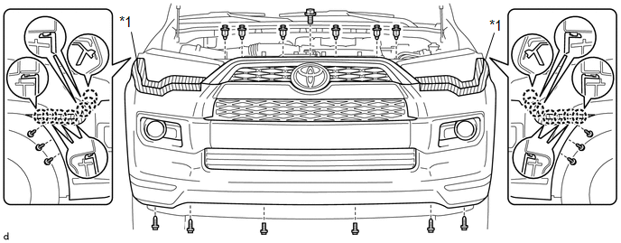
2. REMOVE FRONT BUMPER COVER
(a) Put protective tape around the front bumper cover.
(b) Remove the 3 bolts, 10 screws and 6 clips.
(c) Detach the 14 claws to remove the front bumper cover with radiator grille.
 Text in Illustration
|
*1 |
Protective Tape |
- |
- |
(d) Disconnect 3 connectors.
3. REMOVE UPPER CENTER FRONT BUMPER RETAINER
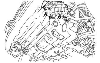
4. REMOVE COOL AIR INTAKE DUCT (for 4WD)
|
(a) Remove the 4 clips and cool air intake duct. |
|
5. REMOVE FRONT BUMPER LOWER COVER
|
(a) Remove the clip. |
|
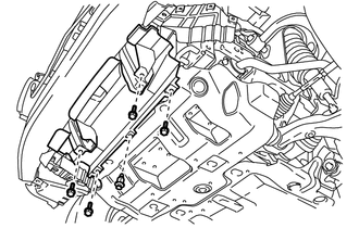
(b) Remove the 4 bolts and front lower bumper cover.
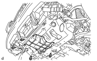
6. REMOVE AIR INTAKE DUCT LH
|
(a) Remove the clip and bolt. |
|
(b) Remove the 2 screws and air intake duct LH.
7. REMOVE AIR INTAKE DUCT RH
HINT:
Use the same procedure as for the LH side.
8. REMOVE RADIATOR SIDE DEFLECTOR LH
9. REMOVE RADIATOR SIDE DEFLECTOR RH
10. REMOVE FRONT BUMPER ENERGY ABSORBER
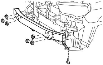
11. REMOVE FRONT BUMPER REINFORCEMENT SUB-ASSEMBLY
|
(a) Remove the screw, 6 nuts and front bumper reinforcement sub-assembly. |
|
12. REMOVE NO. 2 FRONT BUMPER EXTENSION SUB-ASSEMBLY LH
13. REMOVE NO. 2 FRONT BUMPER EXTENSION SUB-ASSEMBLY RH
HINT:
Use the same procedure as for the LH side.
14. REMOVE FRONT BUMPER SIDE SUPPORT LH
15. REMOVE FRONT BUMPER SIDE SUPPORT RH
HINT:
Use the same procedure as for the LH side.
16. REMOVE FRONT BUMPER BRACKET SUB-ASSEMBLY LH
17. REMOVE FRONT BUMPER BRACKET SUB-ASSEMBLY RH
HINT:
Use the same procedure as for the LH side.
 Components
COMPONENTS
ILLUSTRATION
ILLUSTRATION
ILLUSTRATION
ILLUSTRATION
...
 Disassembly
DISASSEMBLY
PROCEDURE
1. REMOVE RADIATOR GRILLE
2. REMOVE NO. 2 ENGINE ROOM WIRE
(a) Disconnect each connector.
(b) Detach the 9 clamps to remove the No. 2 engine room wire.
3. REMOVE NO. 1 ...
Other materials about Toyota 4Runner:
Radio Broadcast cannot be Received or Poor Reception
PROCEDURE
1.
CHECK RADIO AND DISPLAY RECEIVER ASSEMBLY
(a) Check the radio automatic station search function.
(1) Check the radio automatic station search function by activating it.
Result
Proceed to
...
Installation
INSTALLATION
PROCEDURE
1. INSTALL PROPELLER SHAFT ASSEMBLY
(a) Remove SST from the extension housing.
SST: 09325-40010
(b) Install the propeller shaft assembly to the extension housing.
(c) Align the matchmarks on the propeller shaft flange and different ...

0.0075