Toyota 4Runner: Removal
REMOVAL
PROCEDURE
1. REMOVE SPIRAL CABLE SUB-ASSEMBLY
(a) Remove the spiral cable sub-assembly (See page
.gif) ).
).
2. REMOVE WINDSHIELD WIPER SWITCH ASSEMBLY
3. REMOVE HEADLIGHT DIMMER SWITCH ASSEMBLY
|
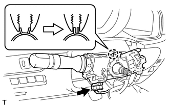
(a) Disconnect the connector. |
|
|
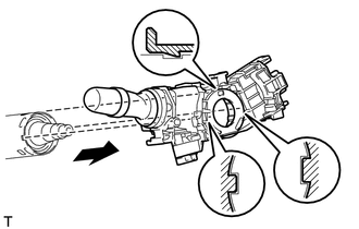
(b) While loosening the band clamp as shown in the illustration, detach the claw to remove the headlight dimmer switch. NOTICE: If the claw is pressed forcefully, it will break. |
|
 Components
COMPONENTS
ILLUSTRATION
...
 Inspection
INSPECTION
PROCEDURE
1. INSPECT HEADLIGHT DIMMER SWITCH ASSEMBLY
(a) Inspect the light control switch.
(1) Measure the resistance according to the value(s) in the table below.
Stan ...
Other materials about Toyota 4Runner:
Relay(w/ Ptc Heater)
On-vehicle Inspection
ON-VEHICLE INSPECTION
PROCEDURE
1. REMOVE PTC HEATER RELAY (PTC NO. 1, PTC NO. 1, PTC NO. 3)
(a) Remove the 3 PTC heater relays from the engine room relay block.
Text in Illustration
*1
...
Removal
REMOVAL
CAUTION / NOTICE / HINT
HINT:
When removing the symbol emblem, No. 1 back door emblem and No. 1 roof side mark,
heat the vehicle body, symbol emblem, No. 1 back door emblem and No. 1 roof side
mark using a heat light.
Standard:
Ite ...

0.0276