Toyota 4Runner: Inspection
INSPECTION
PROCEDURE
1. INSPECT HEADLIGHT DIMMER SWITCH ASSEMBLY
|
(a) Inspect the light control switch. (1) Measure the resistance according to the value(s) in the table below. Standard Resistance:
|
|
(b) Inspect the headlight dimmer switch.
(1) Measure the resistance according to the value(s) in the table below.
Standard Resistance:
|
Tester Connection |
Switch Condition |
Specified Condition |
|---|---|---|
|
11 (HU) - 12 (EL) |
Headlight dimmer switch flash |
Below 1 Ω |
|
17 (HF) - 12 (EL) |
||
|
11 (HU) - 12 (EL) |
Headlight dimmer switch hi beam |
Below 1 Ω |
HINT:
Perform the flash and high beam inspection with the light control switch set to head.
(c) Inspect the turn signal switch.
(1) Measure the resistance according to the value(s) in the table below.
Standard Resistance:
|
Tester Connection |
Switch Condition |
Specified Condition |
|---|---|---|
|
13 (TR) - 12 (EL) |
Turn signal switch right turn |
Below 1 Ω |
|
13 (TR) - 12 (EL) |
Turn signal switch right lane change |
Below 1 Ω |
|
13 (TR) - 12 (EL) |
Turn signal switch neutral |
10 kΩ or higher |
|
15 (TL) - 12 (EL) |
||
|
15 (TL) - 12 (EL) |
Turn signal switch left lane change |
Below 1 Ω |
|
15 (TL) - 12 (EL) |
Turn signal switch left turn |
Below 1 Ω |
(d) Inspect the fog light switch.
(1) Measure the resistance according to the value(s) in the table below.
Standard Resistance:
|
Tester Connection |
Switch Condition |
Specified Condition |
|---|---|---|
|
4 (BFG) - 3 (LFG) |
Fog light switch off |
10 kΩ or higher |
|
4 (BFG) - 3 (LFG) |
Front fog light switch on |
Below 1 Ω |
If the result is not as specified, replace the headlight dimmer switch.
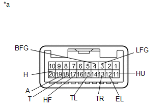
Text in Illustration|
*a |
Component without harness connected (Headlight Dimmer Switch Assembly) |
 Removal
REMOVAL
PROCEDURE
1. REMOVE SPIRAL CABLE SUB-ASSEMBLY
(a) Remove the spiral cable sub-assembly (See page
).
2. REMOVE WINDSHIELD WIPER SWITCH ASSEMBLY
3. REMOVE HEADLIGHT DIMMER SWITCH ASSEM ...
 Installation
INSTALLATION
PROCEDURE
1. INSTALL HEADLIGHT DIMMER SWITCH ASSEMBLY
(a) Install the headlight dimmer switch to the steering column, making
sure that the stopper protrusions and cutout ...
Other materials about Toyota 4Runner:
Removal
REMOVAL
PROCEDURE
1. DISCONNECT CABLE FROM NEGATIVE BATTERY TERMINAL
NOTICE:
When disconnecting the cable, some systems need to be initialized after the cable
is reconnected (See page ).
2. REMOVE FRONT BUMPER COVER (w/o Intuitive Parking Assist System ...
Problem Symptoms Table
PROBLEM SYMPTOMS TABLE
HINT:
Use the table below to help determine the cause of problem symptoms.
If multiple suspected areas are listed, the potential causes of the symptoms
are listed in order of probability in the "Suspected Area" ...

0.0265