Toyota 4Runner: Disassembly
DISASSEMBLY
PROCEDURE
1. REMOVE REAR AXLE SHAFT SNAP RING LH
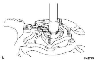
(a) Using a snap ring expander, remove the snap ring.
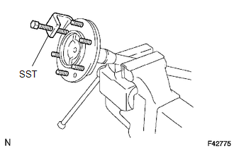
2. REMOVE REAR AXLE SHAFT LH
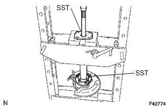
(a) Using SST and a press, press out the rear axle shaft.
SST: 09521-25023
SST: 09521-25011
|
(b) Grind the rear axle bearing retainer using a grinder, and then remove it with a chisel. |
|
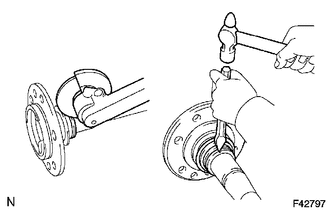
(c) Remove the shaft washer from the axle shaft.
3. REMOVE REAR AXLE HUB AND BEARING ASSEMBLY LH
(a) Temporarily install 4 nuts to the housing bolts.
NOTICE:
Do not use any nuts removed from the vehicle, as they may be damaged.
(b) Using a hammer, remove the 4 housing bolts and rear axle hub and bearing.
(c) Remove the 4 nuts.
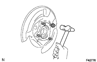
4. REMOVE BRAKE DRUM OIL DEFLECTOR LH
(a) Using SST, remove the 6 hub bolts.
SST: 09650-17011
NOTICE:
- Do not deform the oil deflector.
- Make sure to align the notch of SST with the flange of the oil deflector.
(b) Remove the deflector and deflector gasket from the rear axle shaft.
 Components
COMPONENTS
ILLUSTRATION
ILLUSTRATION
...
 Removal
REMOVAL
CAUTION / NOTICE / HINT
HINT:
Use the same procedure for the RH and LH sides.
The procedure listed below is for the LH side.
PROCEDURE
1. DISCONNECT CABLE FROM NEGATIVE ...
Other materials about Toyota 4Runner:
Reassembly
REASSEMBLY
PROCEDURE
1. INSTALL BRAKE BOOSTER PISTON SIB-ASSEMBLY
(a) Apply a light coat of lithium soap base glycol grease to a new piston.
(b) Install the piston.
NOTICE:
When installing, be careful ...
Installation
INSTALLATION
PROCEDURE
1. INSTALL REAR WIPER MOTOR AND BRACKET ASSEMBLY
(a) Attach the 2 guides and temporally install the rear wiper motor and
bracket assembly with the 3 bolts.
(b) Tighten the ...

0.0066