Toyota 4Runner: Disassembly
DISASSEMBLY
PROCEDURE
1. REMOVE SLIDING ROOF DRIVE GEAR SUB-ASSEMBLY
|
(a) Detach the bracket claw and remove the bracket. |
|
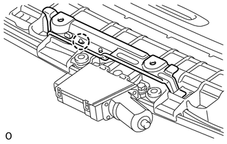
(b) Remove the 2 bolts and drive gear.
2. REMOVE SUNSHADE TRIM SUB-ASSEMBLY
 Text in Illustration
|
*a |
Rearward |
- |
- |
(a) Remove the 2 screws.
(b) Detach the 4 claws and remove the sliding roof piece LH and RH.
(c) Slide and remove the trim.
3. REMOVE SLIDING ROOF SUNSHADE STOPPER LH
|
(a) Remove the stopper. |
|
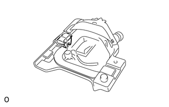
4. REMOVE SLIDING ROOF SUNSHADE STOPPER RH
HINT:
Use the same procedures described for the LH side.
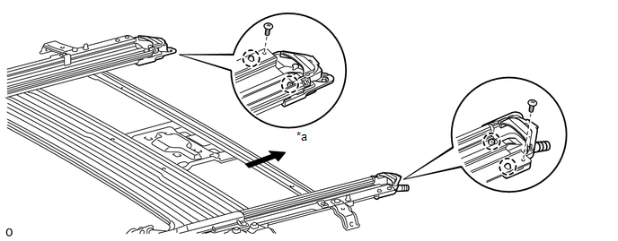
5. REMOVE SLIDING ROOF DRIVE CABLE SUB-ASSEMBLY
NOTICE:
Do not disassemble the sliding roof drive cable sub-assembly except when replacing it.
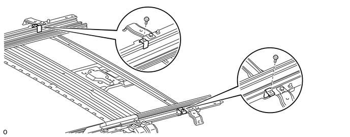
(a) Remove the 2 screws and 2 stoppers.
|
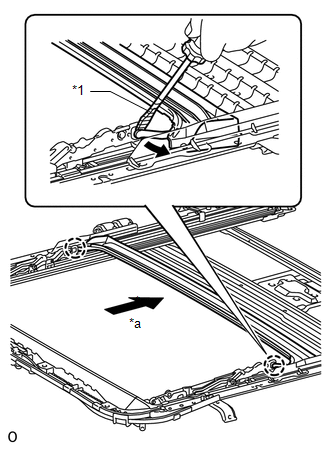
(b) Using a screwdriver, detach the 2 claws and slide the rear roof drip channel rearward to remove it. Text in Illustration
HINT: Tape the screwdriver tip before use. |
|
|
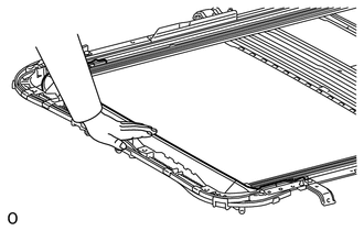
(c) Hold down the window deflector. |
|
|
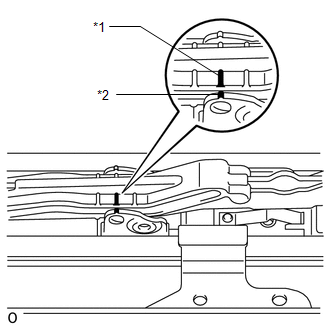
(d) Place matchmarks on the sliding roof drive cable sub-assembly at locations A and B as shown in the illustration. Text in Illustration
|
|
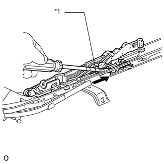
(e) Using a screwdriver, slide the sliding roof drive cable sub-assembly in the direction indicated by the arrow in the illustration to remove it.
 Text in Illustration
|
*1 |
Protective Tape |
.png) |
Slide |
HINT:
Tape the screwdriver tip before use.
 Removal
REMOVAL
PROCEDURE
1. DISCONNECT CABLE FROM NEGATIVE BATTERY TERMINAL
CAUTION:
Wait at least 90 seconds after disconnecting the cable from the negative (-)
battery terminal to disable the SRS sys ...
 Installation
INSTALLATION
PROCEDURE
1. INSTALL SLIDING ROOF HOUSING SUB-ASSEMBLY
(a) Temporarily install the housing with the 8 bolts (vehicle body side) and
8 nuts.
(b) Tighten the 8 nuts in alphabetical or ...
Other materials about Toyota 4Runner:
Luggage compartment features
Cargo hooks
Vehicles with third seats
Fold down the third seats.
Raise the hook to use.
The cargo hooks are provided for securing loose items.
Vehicles without third seats
Raise the hook to use.
The cargo hooks are provided for securing loose items ...
Satellite Radio Broadcast cannot be Selected or After Selecting Broadcast, Broadcast
cannot be Added into Memory
CAUTION / NOTICE / HINT
NOTICE:
Some satellite radio broadcasts require payment. A contract must be
made between a satellite radio company and the user. If the contract expires,
it will not be possible to listen to the broadcast.
PROCE ...

0.0259