Toyota 4Runner: Removal
REMOVAL
PROCEDURE
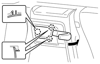
1. REMOVE FRONT DOOR LOWER FRAME BRACKET GARNISH RH
|
(a) Detach the 2 clips and remove the front door lower frame bracket garnish RH. |
|
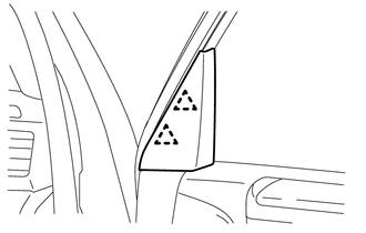
2. REMOVE DOOR NO. 2 INSIDE HANDLE BEZEL RH
|
(a) Using a moulding remover, detach the 3 claws and remove the No.2 inside handle bezel RH as shown in the illustration. |
|
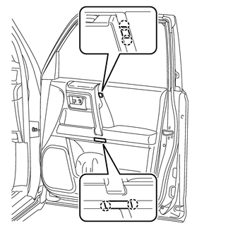
3. REMOVE FRONT DOOR TRIM BOARD SUB-ASSEMBLY RH
|
(a) Detach the 4 claws and 2 door armrest caps. |
|
|
(b) Remove the 3 screws. |
|
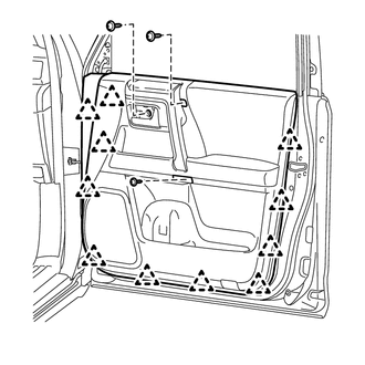
(c) Detach the 11 clips.
|
(d) Pull out the front door trim board sub-assembly RH in the direction indicated by the arrow as shown in the illustration. Text in Illustration
|
|
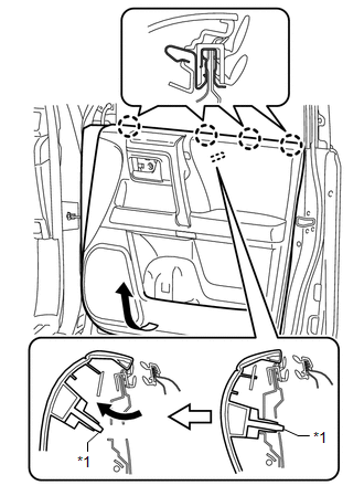
(e) Raise the front door trim board sub-assembly RH to detach the 4 claws and remove the front door trim board sub-assembly RH together with the front door inner glass weatherstrip RH.
|
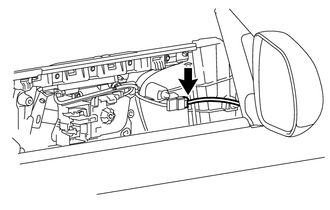
(f) Disconnect the connector. |
|
|
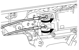
(g) Disconnect the front door lock remote control cable assembly and front door inside locking cable assembly. |
|
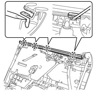
4. REMOVE FRONT DOOR INNER GLASS WEATHERSTRIP RH
|
(a) Using a screwdriver, detach the 4 claws and remove the front door inner glass weatherstrip RH from the front door trim board sub-assembly RH as shown in the illustration. |
|
5. REMOVE DOOR CONTROL SWITCH ASSEMBLY
|
(a) Disconnect the door control switch connector. |
|
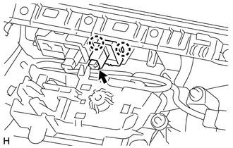
(b) Detach the 2 claws and remove the door control switch assembly.
 Inspection
INSPECTION
PROCEDURE
1. INSPECT DOOR CONTROL SWITCH ASSEMBLY
(a) Measure the resistance according to the value(s) in the table below.
Standard Resistance:
Tester ...
 Installation
INSTALLATION
PROCEDURE
1. INSTALL DOOR CONTROL SWITCH ASSEMBLY
(a) Attach the 2 claws to install the door control switch assembly.
(b) Con ...
Other materials about Toyota 4Runner:
Removal
REMOVAL
PROCEDURE
1. PLACE FRONT WHEELS FACING STRAIGHT AHEAD
2. REMOVE FRONT WHEELS
3. REMOVE NO. 1 ENGINE UNDER COVER SUB-ASSEMBLY
Click here
4. REMOVE REAR ENGINE UNDER COVER ASSEMBLY
Click here
5. REMOVE FRONT DIFFERENTIAL CARRIER ASSEMBLY (for ...
Theft Deterrent System Communication Line High Fixation (B279A)
DESCRIPTION
If the communication line (EFIO-IMI) to the ID code box is stuck on HI output,
the ECM stores this DTC.
DTC Code
DTC Detection Condition
Trouble Area
B279A
The communication line (EFI ...

0.0271