Toyota 4Runner: Installation
INSTALLATION
PROCEDURE
1. INSTALL DOOR CONTROL SWITCH ASSEMBLY
|
(a) Attach the 2 claws to install the door control switch assembly. |
|
.png)
(b) Connect the door control switch connector.
2. INSTALL FRONT DOOR INNER GLASS WEATHERSTRIP RH
|
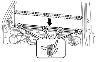
(a) Install the front door inner glass weatherstrip RH. |
|
3. INSTALL FRONT DOOR TRIM BOARD SUB-ASSEMBLY RH
|
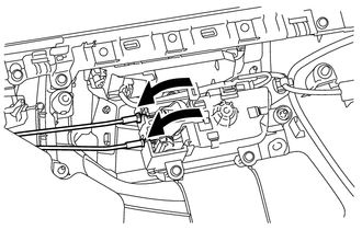
(a) Connect the front door lock remote control cable assembly and front door inside locking cable assembly. |
|
|
(b) Connect the connector. |
|
.png)
|
(c) Attach the front door trim board sub-assembly to the 4 claws of the front door inner glass as shown in the illustration. |
|
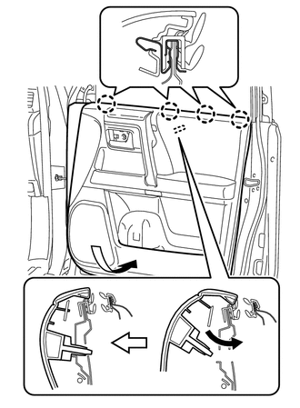
(d) Attach the 11 clips to install the front door trim board sub-assembly RH.
(e) Install the 3 screws.
(f) Attach the 4 claws to install the 2 door armrest caps.
4. INSTALL DOOR NO. 2 INSIDE HANDLE BEZEL RH
(a) Attach the 3 claws to install the No.2 inside handle bezel RH.
5. INSTALL FRONT DOOR LOWER FRAME BRACKET GARNISH RH
(a) Attach the 2 clips to install the front door lower frame bracket garnish RH.
 Removal
REMOVAL
PROCEDURE
1. REMOVE FRONT DOOR LOWER FRAME BRACKET GARNISH RH
(a) Detach the 2 clips and remove the front door lower frame bracket
garnish RH.
...
 Door Control Transmitter(w/ Smart Key System)
Components
COMPONENTS
ILLUSTRATION
Removal
REMOVAL
CAUTION / NOTICE / HINT
NOTICE:
Take extra care when handling these precision electronic components.
PROCEDURE
1. REMOVE TRANSMITTER B ...
Other materials about Toyota 4Runner:
System Description
SYSTEM DESCRIPTION
1. WINDSHIELD DEICER SYSTEM DESCRIPTION
The windshield deicer system thin heater wires are attached to the inside of
the front window and deice the window surface quickly. The indicator light illuminates
while the system is operating. ...
Open in Stop Light Switch Circuit (C1425)
DESCRIPTION
The skid control ECU receives the stop light switch assembly signal and detects
the brake pedal operation status.
The skid control ECU has an open detection circuit, which stores this DTC if
it detects an open in the stop light input line of ...

0.0072