Toyota 4Runner: Removal
REMOVAL
CAUTION / NOTICE / HINT
HINT:
- Use the same procedure for the RH and LH sides.
- The procedure listed below is for the LH side.
PROCEDURE
1. DISCONNECT CABLE FROM NEGATIVE BATTERY TERMINAL
NOTICE:
When disconnecting the cable, some systems need to be initialized after the cable
is reconnected (See page .gif) ).
).
2. REMOVE REAR DOOR INSIDE HANDLE BEZEL LH
3. REMOVE REAR DOOR TRIM BOARD SUB-ASSEMBLY LH
4. REMOVE REAR DOOR INNER GLASS WEATHERSTRIP LH
5. REMOVE REAR DOOR SERVICE HOLE COVER LH
6. REMOVE REAR DOOR GLASS RUN LH
7. REMOVE REAR DOOR REAR LOWER WINDOW FRAME SUB-ASSEMBLY LH
8. REMOVE REAR DOOR QUARTER WINDOW GLASS LH
9. REMOVE REAR DOOR GLASS SUB-ASSEMBLY LH
10. REMOVE REAR DOOR LOCK ASSEMBLY LH
|
(a) Using a T30 "TORX" wrench, remove the 3 screws. |
|
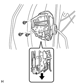
(b) Move the rear door lock assembly downward, pull the release plate out of the rear door outside handle frame, and remove the rear door lock assembly and cables as a unit.
(c) Remove the door lock wiring harness seal from the rear door lock assembly.
11. REMOVE REAR DOOR LOCK REMOTE CONTROL CABLE ASSEMBLY LH
12. REMOVE REAR DOOR INSIDE LOCKING CABLE ASSEMBLY LH
 Components
COMPONENTS
ILLUSTRATION
ILLUSTRATION
...
 Inspection
INSPECTION
PROCEDURE
1. INSPECT REAR DOOR LOCK ASSEMBLY LH
(a) Check the door lock motor operation.
(1) Apply battery voltage to the door lock motor and check the operation
of the d ...
Other materials about Toyota 4Runner:
Steering Angle Sensor Communication Stop Mode
DESCRIPTION
Detection Item
Symptom
Trouble Area
Steering Angle Sensor Communication Stop Mode
Either condition is met:
"Spiral cable (Steering Angle Sensor)" is not displayed ...
On-vehicle Inspection
ON-VEHICLE INSPECTION
PROCEDURE
1. INSPECT BRAKE MASTER CYLINDER FLUID PRESSURE CHANGE
(a) Inspect the battery voltage.
Battery voltage:
11 to 14 V
(b) Turn the ignition switch off and depres ...

0.0146