Toyota 4Runner: Removal
REMOVAL
PROCEDURE
1. TABLE OF BOLT, SCREW AND NUT
HINT:
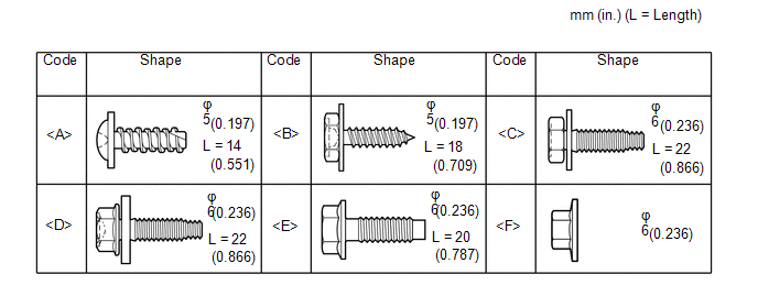
All bolts, screws and nuts relevant to installing and removing the instrument panel are shown along with their alphabet code in the table below.
2. DISCONNECT CABLE FROM NEGATIVE BATTERY TERMINAL
CAUTION:
Wait at least 90 seconds after disconnecting the cable from the negative (-) battery terminal to disable the SRS system.
NOTICE:
When disconnecting the cable, some systems need to be initialized after the cable
is reconnected (See page .gif) ).
).
3. REMOVE HEADLIGHT DIMMER SWITCH ASSEMBLY
(See page )
4. REMOVE REAR CONSOLE BOX ASSEMBLY
(See page )
5. REMOVE DOOR SCUFF PLATE ASSEMBLY LH
6. REMOVE DOOR SCUFF PLATE ASSEMBLY RH
HINT:
Use the same procedure as for the LH side.
7. REMOVE COWL SIDE TRIM BOARD LH
8. REMOVE COWL SIDE TRIM BOARD RH
HINT:
Use the same procedure as for the LH side.
9. REMOVE FRONT DOOR OPENING TRIM WEATHERSTRIP LH
10. REMOVE FRONT DOOR OPENING TRIM WEATHERSTRIP RH
HINT:
Use the same procedure as for the LH side.
11. REMOVE ASSIST GRIP PLUG
12. REMOVE NO. 1 ASSIST GRIP
13. REMOVE FRONT PILLAR GARNISH RH
14. REMOVE FRONT PILLAR GARNISH LH
15. REMOVE LOWER INSTRUMENT PANEL FINISH PANEL ASSEMBLY
|
(a) w/o Smart Key System: (1) Detach the 4 clips. (2) Disconnect the cooler thermistor and remove the lower instrument panel finish panel assembly. |
|
|
(b) w/ Smart Key System: (1) Detach the 4 clips. (2) Disconnect the connector and cooler thermistor and remove the lower instrument panel finish panel assembly. |
|
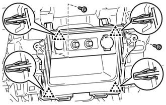
16. REMOVE NO. 2 SWITCH HOLE BASE
|
(a) Detach the 6 clips and 2 guides. |
|
(b) Disconnect each connector and remove the No. 2 switch hole base.
17. REMOVE INSTRUMENT CLUSTER FINISH PANEL SUB-ASSEMBLY
|
(a) Detach the 7 clips to remove the instrument cluster finish panel sub-assembly. |
|
18. REMOVE COMBINATION METER ASSEMBLY
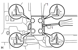
19. REMOVE LOWER INSTRUMENT PANEL FINISH PANEL SUB-ASSEMBLY
|
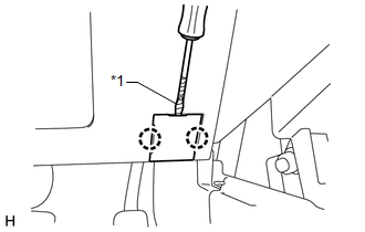
(a) Using a screwdriver, detach the 2 claws to open the cover. Text in Illustration
HINT: Tape the screwdriver tip before use. |
|
|
(b) Remove the 2 bolts <C>. |
|
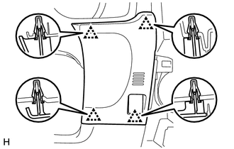
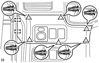
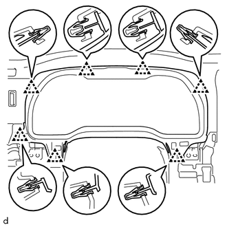
(c) Detach the 13 clips and 2 guides.
(d) Disconnect each connector and hood lock control cable assembly and remove the lower instrument panel finish panel sub-assembly.
20. REMOVE LOWER NO. 1 INSTRUMENT PANEL AIRBAG ASSEMBLY
21. REMOVE NO. 2 INSTRUMENT PANEL UNDER COVER SUB-ASSEMBLY
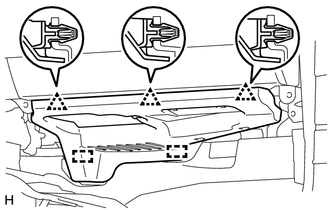
|
(a) Detach the 3 clips and 2 guides to remove the No. 2 instrument panel under cover sub-assembly. |
|
22. REMOVE LOWER INSTRUMENT COVER LH
|
(a) Put protective tape around the lower instrument cover LH. |
|
(b) Using a screwdriver, detach the 4 claws to remove the lower instrument cover LH.
Text in Illustration|
*1 |
Protective Tape |
HINT:
Tape the screwdriver tip before use.
23. REMOVE LOWER NO. 2 INSTRUMENT PANEL AIRBAG ASSEMBLY
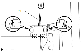
24. REMOVE INSTRUMENT PANEL BOX DOOR COVER
|
(a) Using a screwdriver, detach the 2 claws and 2 guides to remove the instrument panel box door cover. Text in Illustration
HINT:
|
|
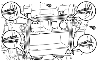
25. REMOVE LOWER INSTRUMENT PANEL SUB-ASSEMBLY
|
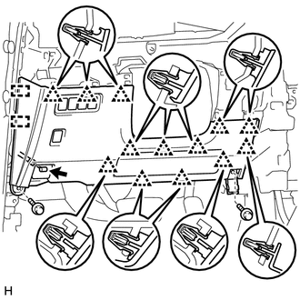
(a) Remove the 3 screws <B> and 2 bolts <C>. |
|
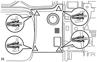
(b) Detach the 10 clips and guide.
(c) Disconnect each connector and remove the lower instrument panel sub-assembly.
26. REMOVE HEATER CONTROL ASSEMBLY
27. REMOVE RADIO AND DISPLAY RECEIVER ASSEMBLY WITH BRACKETS (for Radio and Display Type)
28. REMOVE NAVIGATION RECEIVER ASSEMBLY WITH BRACKETS (for Navigation Receiver Type)
29. REMOVE LOWER CENTER INSTRUMENT CLUSTER FINISH PANEL SUB-ASSEMBLY (w/o Climate Control Seat System)
|
(a) Remove the 2 screws <B>. |
|
(b) Detach the 4 clips.
(c) Disconnect 2 connectors and remove the lower center instrument cluster finish panel sub-assembly.
30. REMOVE LOWER CENTER INSTRUMENT CLUSTER FINISH PANEL SUB-ASSEMBLY (w/ Climate Control Seat System)
|
(a) Remove the 2 screws <B>. |
|
(b) Detach the 4 clips.
(c) Disconnect 3 connectors and remove the lower center instrument cluster finish panel sub-assembly.
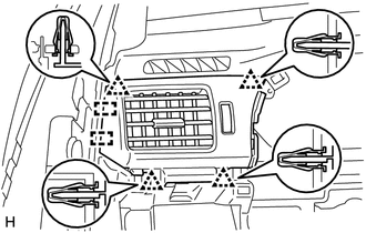
31. REMOVE NO. 1 INSTRUMENT PANEL REGISTER ASSEMBLY
|
(a) Detach the 4 clips and 2 guides to remove the No. 1 instrument panel register assembly. |
|
32. REMOVE NO. 2 INSTRUMENT PANEL REGISTER ASSEMBLY
HINT:
Use the same procedure as for the No. 1 instrument panel register assembly.
33. REMOVE NO. 1 INSTRUMENT PANEL SPEAKER PANEL SUB-ASSEMBLY
|
(a) Put protective tape around the No. 1 instrument panel speaker panel sub-assembly. |
|
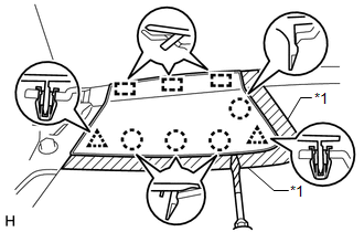
(b) Using a screwdriver, detach the 2 clips, 4 claws and 3 guides to remove the No. 1 instrument panel speaker panel sub-assembly.
Text in Illustration|
*1 |
Protective Tape |
HINT:
Tape the screwdriver tip before use.
34. REMOVE NO. 2 INSTRUMENT PANEL SPEAKER PANEL SUB-ASSEMBLY
|
(a) Put protective tape around the No. 2 instrument panel speaker panel sub-assembly. |
|
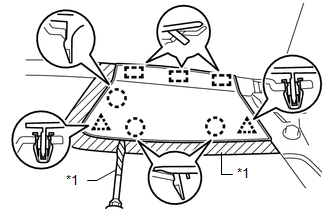
(b) Using a screwdriver, detach the 2 clips, 3 claws and 3 guides to remove the No. 2 instrument panel speaker panel sub-assembly.
Text in Illustration|
*1 |
Protective Tape |
HINT:
Tape the screwdriver tip before use.
35. REMOVE FRONT NO. 2 SPEAKER ASSEMBLY
36. REMOVE DCM (TELEMATICS TRANSCEIVER)
37. REMOVE 4 WHEEL DRIVE CONTROL ECU NO. 2 (for 4WD)
(a) for VF2A:
Remove the 4 wheel drive control ECU No. 2 (See page
).
(b) for VF2BM:
Remove the 4 wheel drive control ECU No. 2 (See page
).
(c) for VF4BM:
Remove the 4 wheel drive control ECU No. 2 (See page
).
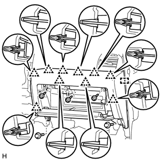
38. REMOVE INSTRUMENT PANEL SUB-ASSEMBLY
(a) Remove the 6 bolts <E> and nut <F>.
(b) Remove the 2 passenger airbag bolts and bolt labeled A.
(c) Disconnect each connector and detach the clamps and claws.
(d) Detach the 2 guides and remove the instrument panel sub-assembly.
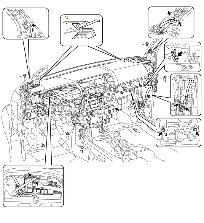 Text in Illustration
|
*1 |
Bolt <E> |
*2 |
Nut <F> |
|
*3 |
Guide |
*4 |
Passenger Airbag Bolt |
|
*5 |
Bolt A |
- |
- |
 Components
COMPONENTS
ILLUSTRATION
ILLUSTRATION
ILLUSTRATION
ILLUSTRATION
ILLUSTRATION
ILLUSTRATION
ILLUSTRATION
...
 Disassembly
DISASSEMBLY
PROCEDURE
1. REMOVE NO. 1 HEATER TO REGISTER DUCT
(a) Remove the 4 screws and No. 1 heater to register duct.
2. REMOVE NO. 2 HEATER ...
Other materials about Toyota 4Runner:
Crawl Indicator Light does not Come ON
DESCRIPTION
If any of the following conditions are met, the crawl indicator light blinks
and crawl control is stopped.
Crawl control is operated when the vehicle stability control system
is malfunctioning, or a vehicle stability control system m ...
Rear Coil Spring
Components
COMPONENTS
ILLUSTRATION
Removal
REMOVAL
CAUTION / NOTICE / HINT
HINT:
Use the same procedure for the RH and LH sides.
The procedure listed below is for the LH side.
PROCEDURE
1. REMOVE REAR WHEEL
2. REMOVE REAR STAB ...

0.0263